Using the layers
Basic layer settings
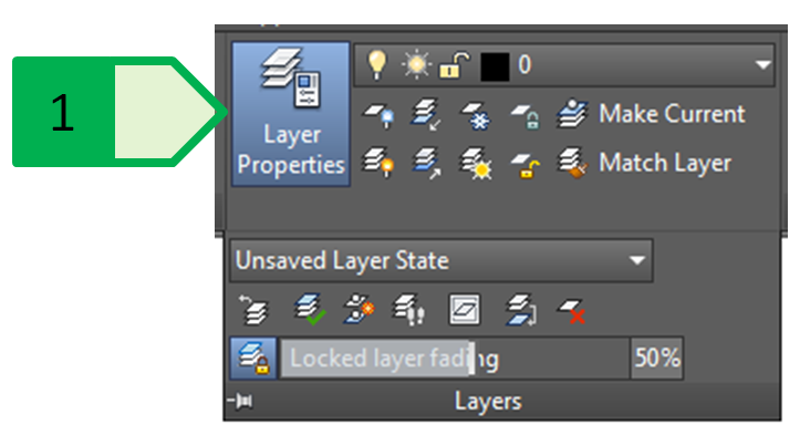
The “Layers” panel on the “Home” tab is used to work with the layers. (Fig. 61). To manage the existing, or to create new layers, we use the “Layer properties” button or the command “LAYER” which opens or hides the manager palette for the properties of the layers.

Fig. 61: “Layers” palette to work with the layers, 1 - “Layer properties” button
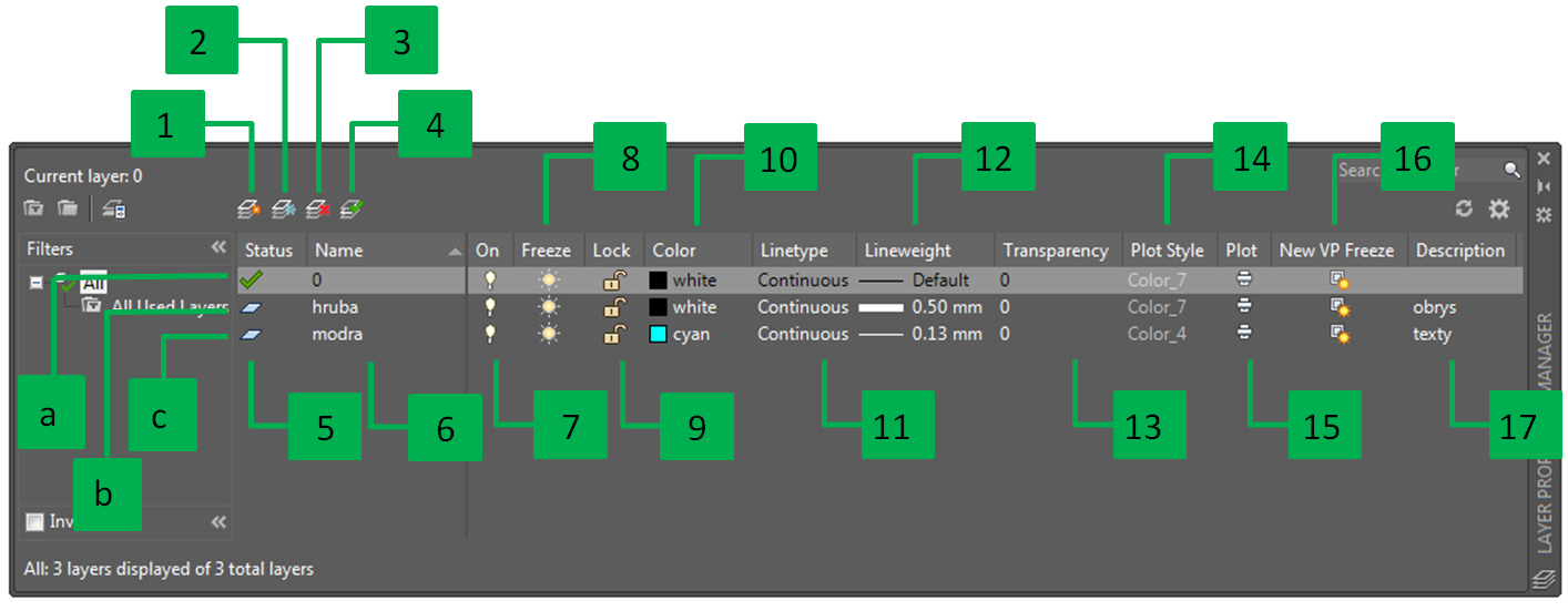
The manager palette for the properties of the layers (Fig. 62) displays all the layers that are in the current drawing, including the external reference layers, and allow us to manage the individual layers.

Fig. 62: Layer manager palette for the properties of the layers
We can create a new layer in two ways:
- by creating a new layer (Fig. 62 - 1), it creates a new layer which will have the same pre-set parameters as the current layer (colour, thickness and type of the line, etc.),
- by creating a new layer (Fig. 62 - 2), it creates a new layer which will have the same pre-set parameters as the current layer (colour, thickness and type of the line, etc.) and that will be frozen in all viewports (see chapter “Layers and viewports”).
The removal of the layer (Fig. 62 - 3) allows removing the layers, except for the following layers:
- layer “0” and layer “Defpoints”; in the layer “Defpoints”, there are the points showing the dimensional lengths, the layer is created automatically after the creation of the first dimension in the drawing , then it cannot be removed, even after all the dimensions have been removed from the drawing,
- current layer,
- layer in which there is at least one object; also applies to objects created in a block that is created in the drawing but is not inserted into the drawing,
- layers of the external references.
The setting of the current layer can be done by double-clicking on the name of the layer in the layers palette (Fig. 62 - 6) or by clicking the icon in the layers palette to set the selected layer as the current one (Fig. 62 - 4).
The layers can be in three states:
- the current level is marked with a green tick in the column for the layer status (Fig. 62 - a),
- the layer in which there is at least one object - grey pictogram (Fig. 62 - b),
- the layer in which there are no objects - blue pictogram (Fig. 62 - c).
The name of the created layers (Fig. 62 - 6) can be changed for all levels, except for the layer “0” and the layers of the external references.
The layers can be turned on and off (Fig. 62 - 7) for the whole drawing. The turned-off layers will not be displayed in the drawing and will not be printed. The current layer may be turned off, so the objects are automatically not displayed until we turn on this layer. The existing object can be transferred to the turned-off layer from another layer. This function only controls the physical display of the objects, but the program still re-calculates the parameters of the turned-off objects, which can cause slower running of the program on large drawings. Also, when selecting objects through quick selection or selecting all objects (shortcut Ctrl + A), you can also select objects in the turned-off layers.
The layers can be frozen or unfrozen (Fig. 62 - 8) for the whole drawing (model space and all viewports). The current layer cannot be frozen and the existing object can be transferred to the frozen layer from another layer. The frozen layers will not be displayed in the drawing, and the program will not re-calculate them when zooming, sliding the drawing, etc. When selecting objects through quick selection or selecting all objects (shortcut Ctrl + A), you cannot select objects in the frozen layers. The specific behaviour of frozen layers is also manifested in the blocks (see chapter “Working with layers and blocks”).
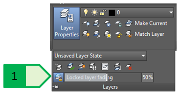
The layers can be locked and unlocked (Fig. 62 - 9) for the whole drawing. The turned-off layers will be displayed in the drawing and printed but it is not possible to edit or remove the objects in these layers. This functionality is used especially for objects that are fixed and cannot be changed - for example, planimetry, topography, existing lines or objects, etc. which have to be taken into account when working on the project (for measuring distances, determining parameters of coordinates, lengths, number of objects, etc.), but it is important not to edit them (by mistake or on purpose). The current layer can be locked and the existing object can be transferred to the locked layer from another layer. The objects in the locked layer are displayed in a faded colour. The rate of the colour fading of the locked layers is expressed in percentages from 0 to 90 (the default setting is 50), and it is determined by the variable “LAYLOCKFADECTL”, which can be started using the command line and entering a new value or setting the colour fading using the slider, or by entering the percentage value on the “Layers” panel on the “Home” tab (Fig. 63).

Fig. 63: Fading of the object colour in the locked layer, 1 - slider and numerical value for the colour fading
For the layers, is possible to set one colour (Fig. 62 - 10). We can use index colours (pre-defined), use the system for the selection of true colours controlled by the RGB or HSL colour model, or use the selection from the colour libraries RAL, PANTONE, DIC Colour Guide (Fig. 64).

Fig. 64: Selection of the colour layer, 1 - index colours; 2 - true colours; 3 - colour libraries
For the layers, it is possible to select one of the various line types (Fig. 62 - 11). When selecting the lines, it is possible to select the lines defined in the file *.lin and the associated file *.shx (Fig. 65). The line structure is defined by this pair of files and the display mode, or the size of line components (space, line, dot, etc.) is controlled by the variables of the total scale of the drawing, the total scale of the drawing lines, and the total scale of the lines of a particular object.

Fig. 65: Selection of the line type. List of lines loaded in the drawing (on the left); Window for loading the lines from the respective file *.lin (on the right).
Each layer can have one of the different line thicknesses (Fig. 62 - 12). The pre-set line thickness “Default” is set to the value of 0.25 mm and can be changed globally for the whole program using the variable LWDEFAULT, giving the number of hundredths of millimetres - the pre-set thickness 0.25 mm is then set to 25. The display of the line thickness is controlled by the switch (Fig. 66) or by setting the variable LWDISPLAY.

Fig. 66: Controlling the display of the line thickness in the drawing, 1 - switch for the display of the line thickness
The transparency of the layers (Fig. 62 - 13) is defined as a percentage and can have the value of 0 – 90.
The printing style (Fig. 62 - 14) defines the colour in which the layer is printed. By default, this value matches the index colour.
The setting of the layer printing (Fig. 62 - 15) determines whether the objects in the given layer are printed or not. This function is suitable for creating auxiliary constructions and notes that appear in the program but will not be printed.
The setting of the freeze in the newly created viewport (Fig. 62 - 16) defines whether the layer in the newly created viewport is automatically frozen.
The layer can be assigned a description (Fig. 62 - 17) that will simplify the user’s identification of the purpose for which the layer should be used.
Layer filters
If necessary, it is possible to create layer filters based on their properties or by grouping the layers. This organized structure allows faster and more efficient work with the created layers.
In case of the new part of the municipality of Veľký Lapáš, the engineering networks and connections are created in the respective layers. By creating a filter for the layer groups (Fig. 67) for public lines and connections, it is possible to quickly modify the turning on and off, freezing and unfreezing or locking and unlocking all the layers at once, as well as browsing the settings for only these layers - this function is used in the local menu which will be displayed for the given filter by clicking the right button on the required filter. When creating a groups filter, the layers are not moved from the list of all layers (filter of layer groups) or from the list of all the layers used (the filter of layer properties) as each layer can be included in multiple filters.

Fig. 67: Using the layer filters. All layers (on the left); Created group of connections layers (in the middle); Local menu to set the turning off or freezing all layers in the group of connection layers (on the right).
Other tools for working with layers
The “Layers” panel offers additional tools for working with the existing layers (Fig. 68).

Fig. 68: Other tools for working with the existing layers
Other tools for working with layers
|
Tool |
Description |
|
1 |
turns off all the layers in the drawing |
|
2 |
turns on all the layers in the drawing |
|
3 |
isolates the layer of the selected object - turns off or locks (the setting is done using the command line) all the layers in the drawing, except for the layer of the selected object |
|
4 |
restores the state of the turning on or locking of all levels before using the isolation of the layer of the selected object |
|
5 |
freezes all the layers in the drawing |
|
6 |
unfreezes all the layers in the drawing |
|
7 |
locks all the layers in the drawing |
|
8 |
unlocks all the layers in the drawing |
|
9 |
sets the layer of the selected object as the current layer |
|
10 |
moves the selected layer to the layer of the object of another selected object |
|
11 |
returns the last change in the settings of the layers (colour, thickness, turning on/off, etc.) |
|
12 |
moves the selected object into the current layer |
|
13 |
creates a copy of the selected object and moves that copy to the selected object layer |
|
14 |
allows to browse the list of layers - the selected layers will be displayed and the others will be hidden - it will be valid during the command, after the ending, the status can be returned to the initial setting |
|
15 |
freezes the layer of the selected object in all viewports, except for the current one |
|
16 |
joins the layers of selected objects to the target layer and clears the original layers |
|
17 |
deletes the objects and the layer of the selected object |
|
18 |
starts the manager of the layer status settings that allows to save or restore the status of the layers (colour, thickness, turning off, etc.) according to the required properties |
Working with layers and blocks
When working with the layers and blocks, it is necessary to take into account several specific parameters and to be aware of the basic principles that are connected with the solution of the blocks. First of all, it is necessary to be aware that a block made up of one or more entities is inserted in a given layer after insertion, independently of the layers of the individual entities that make up this block.
In the situation drawing of the new part of the municipality Veľký Lapáš, after the re-definition, there are several copies of the block “hatch_circular” with a detailed view of the sewer hatch, which is formed by a group of objects - lines, circles and arcs, all objects being in the “thin” layer.
If some objects that make up this block are transferred to a different layer, the change will immediately appear in all copies of this block, and each of these blocks was transferred to a different layer (Fig. 69).

Fig. 69: Changing the layers of the block objects, 1 - object (circle) in the “thick” layer of green colour; 2 - object (circle) in the “dotted” layer of blue colour; a - block in the “thick” layer; b - block in the “thin” layer; c - block in the “dotted” layer
The layer in which the block is located does not affect the display of these blocks now. But if the “thick” layer is turned off, a circle that is in that layer disappears in each block, but the block that is completely in that layer will be displayed, except for the green circle in the turned-off “thick” layer (Fig. 70).

Fig. 70: Effect of the turned-off layer on the display of the blocks, 1 - turned-off “thick” layer; 2 - pictogram of the turned-off layer (bulb); a - block in the “thick” layer; b - block in the “thin” layer; c - block in the “dotted” layer
But if we freeze the “dotted” layer, then a circle in the “dotted” layer disappears in each block, but also the block that is in completely in this layer will disappear (Fig. 71).

Fig. 71 Effect of the frozen layer on the display of the blocks, 1 - frozen “dotted” layer; 2 - pictogram of the frozen layer (flake); a - block in the “thick” layer; b - block in the “thin” layer; c - block in the “dotted” layer is not displayed
The “0” layer has specific properties that are reflected in the blocks so that the objects in the “0” layer, that make up the block, take the parameters of the colour, thickness, line type and transparency according tot he layer in which the whole block is placed. If we modify the hatch block so that part of the drawing objects displaying the anti-skid surface finish of the hatch moves to the “0” layer, these objects take the colour, line type and thickness according to the layer where the whole block is placed (Fig. 72).

Fig. 72: Behaviour of the “0” layer in the blocks. Objects in the “0” layer displayed in black colour in the definition of the block (on the left); a - block in the “thick” layer; b - block in the “thin” layer; c - block in the “dotted” layer
The objects in the “0” layer respond to the turning off and freezing in the same way as the objects that are placed in the turned-off and unfrozen layer (Fig. 73).

Fig. 73: Objects in the “0” layer and their behaviour during the turning off and freezing of the layer in which the whole block is placed. a- block in the “thick” layer - object in the “0” layer are turned off; b - block in the “thin” layer - objects in the “0” layer are displayed in the “thin” layer; c - block in the “dotted” layer is not displayed.
Taking the properties of the colour, line type, thickness or transparency, as described at the “0” layer, can be achieved when the object in the block is in a layer other than “0” but the parameter of the colour, thickness and line type as well as transparency will be set to the value “ByBlock” (Fig. 74).

Fig. 74: Setting the object properties according to the selected parameters of the block, 1 - changed objects; 2 - colour; 3 - line type; 4 - thickness; 5 - transparency
If the object has one of the parameters set to “ByBlock” this setting will be reflected by the layer in which the block is created. Compared with the behaviour of the “0” layer, when the layer in which the block is placed is turned off, the parameters set to the value “ByBlock” become evident (Fig. 75).

Fig. 75: Parameter “ByBlock”. a- block in the “thick” layer; b - block in the “thin” layer; c - block in the “dotted” layer; 1 - turned-off “thick” layer; 2 - turned-off “dotted” layer. The objects of the outer ring in the hatch block are displayed as thick and green, or thin and blue in the objects a. and c. because they have taken only the parameters of the colour, thickness, line type and transparency.