Possibilities of linking CAD and GIS
At present, similar to the CAD applications, various GIS programs can be used to work with raster, vector, or general database information. Some programs are charged, others may be licensed under the conditions of the licences of the GNU Free Software. The adjective “free” means that users can copy, modify, and distribute it without any limitations.
In order to understand the basic options for linking and using CAD and GIS, we will work with the QGIS GNU software.
Importing the CAD data into the GIS environment
In the GIS environment, we can generally talk about three basic elements of geometry:
- points
- lines
- areas
For the documentation in the CAD file format (*.dwg or *.dxf), documentation is also made up of various other types of objects (dimensions, texts, blocks, tables, hatches, etc.), which may cause generalization or replacement by other types of objects during the import into the GIS environment.
The import of the CAD data into the GIS environment will be explained using the situation drawing of the Radošinka stream. The data in the CAD file format can be loaded into the QGIS environment in the *.dxf file format, so we need to save this drawing in this format.
As we work with the drawing documentation in the S-JTSK coordinate system in the Krovak view, it is necessary to create a QGIS project in this coordinate system. Our coordinate system is S-JTSK (Greenwich)/Krovak East North, EPSG: 102067. We link the basic map of the Slovak Republic as a WM layer to the project (link: http://nipi.sazp.sk/arcgis/services/podklady/zbgis10r/MapServer/WMSServer/?), with which we will continue to work together with the documentation of the Radošinka watercourse (Fig. 105). The coordinate system is S-JTSK (Greenwich)/Krovak East North, EPSG: 5514, at the time of processing this study material, had problems with the use of the Basic Map of the SR when it was connected to the WMS server, so the EPSG 102067 coordinate system has been selected for the project.
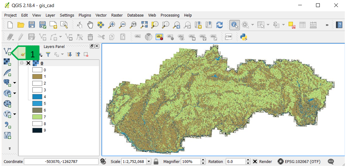
Fig. 105: Project in the QGIS environment - Basic Map of the SR linked via the WMS server. 1 - tool for adding vector data
It is then possible to load the *.dxf file with the situation of the Radošinka stream using the “Add Vector Layer” tool in the same way as when loading the *.shp files used in the GIS programs.
Since *.dxf as a file does not have a defined coordinate system but the drawing contained in it is prepared in the S-JTSK coordinate system, it is necessary to select a suitable coordinate system (Fig. 106) - in this case, it is also possible to select the EPSG 5514 coordinate system, since the coordinate system of the added file is defined and not of the whole project.
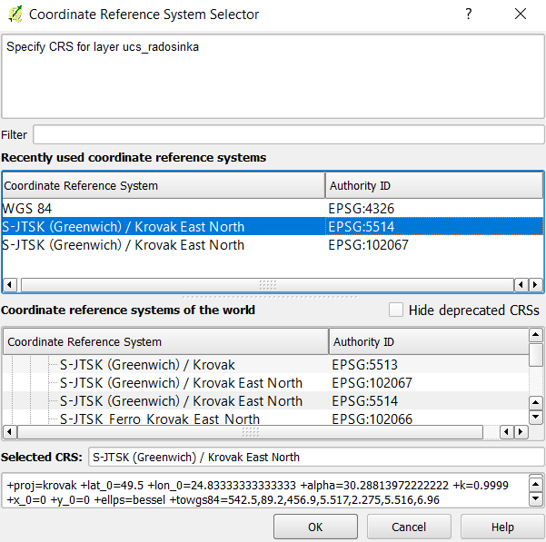
Fig. 106: Selection of the coordinate system of the added *.dxf file in the QGIS environment
Since the *.dxf file contains, or may contain various types of geometry, it is necessary to select a type of geometry to be added from the required *.dxf file to the QGIS project, while it is possible to select several types geometry by holding down the Ctrl key and by selecting using the mouse in the list of possible types of geometry (Fig. 107) - in case of the Radošinka stream, we need to add line objects, so we select the “LineString” option to add the line objects.
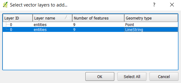
Fig. 107: Selection of the type of geometry for the objects to be added to the project
Then, we will re-select the coordinate system for the added objects (either EPSG 5514 or EPSG 102067), and all the line objects (as well as arcs, circles, ellipses, and others) will be added to the project. Adding the objects ignores the tuning on/off or freezing/unfreezing the layers of the *.dxf file, and it adds all the objects of the selected type to the project (Fig. 108).
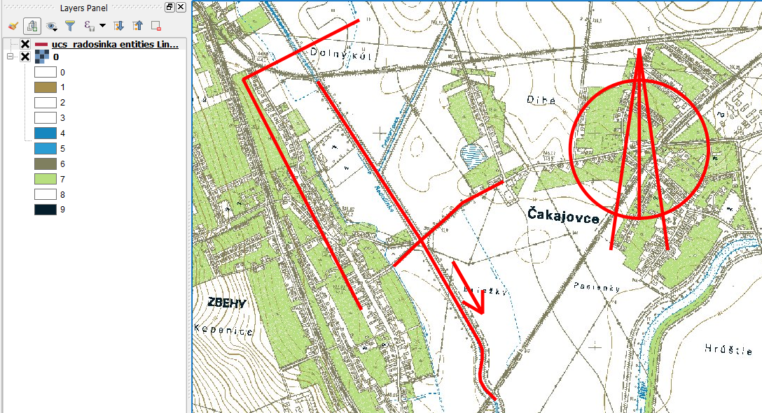
Fig. 108: Line objects inserted into QGIS - their displaying on the WMS background of the Basic Map of the SR
The *.dxf file imported in this way can then be stored in the QGIS environment in various formats, such as *.shp, and its content can be used and processed for intended purposes (analyses, map outputs, etc.).
Exporting the GIS data into the CAD environment
The data from the GIS environment can be exported as needed to the CAD environment, where it is possible to integrate them according to the project documentation. In this way, for example, it is possible to take the boundaries of the territory from historical maps, the way of land use, the landscape structure from the orthophotomap, to take the vector polygon layer of the cadastral map and others.
In case of the Radošinka stream, we take the course of the melioration channels from the Basic Map into the drawing of the Radošinka stream. We will work with the project in which we have imported the *.dxf file of the Radošinka stream crossing the road which connects the villages Zbehy and Čakajovce.
In the existing project, we will create a new *.shp file in which the line objects of both meliorating channels will be created, the coordinate system of the layer will be EPSG 5514 and in this layer we will create two line objects - each of them will represent one channel (Fig. 109).
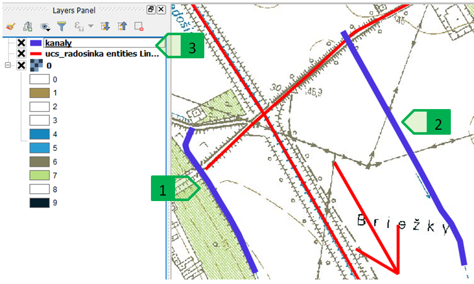
Fig. 109: Creating the newlines - channels, 1 - channel no. 1; 2 - channel no. 2; 3 - newly created layer of the channels
The objects created in this way can then be saved in the *.dxf format. By right-clicking the desired layer we will activate the local menu, where we select the “Save as” option to open the dialogue box for storing the respective layer. In this window we select the file format (AutoCAD DXF), the storage location and the coordinate system (EPSG 5514 or EPSG 102067), and we save the file (Fig. 110). The file is then added to the current QGIS project.
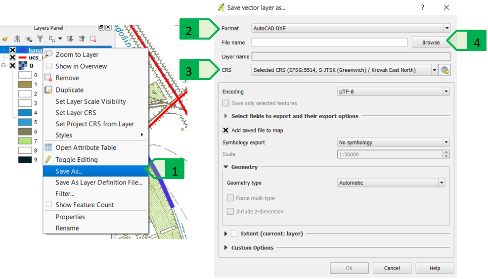
Fig. 110: Saving the requested *.dxf file, 1 - “Save as ...” menu; 2 - setting the *.dxf format for the new file; 3 - setting the coordinate file of the new file; 4 - setting the location of the new file
The newly created file can then be opened in the AutoCAD program. As we exported only the layer of new channels, this newly created *.dxf file will not contain anything else other than the two objects of the “Polyline” type (Fig. 111).
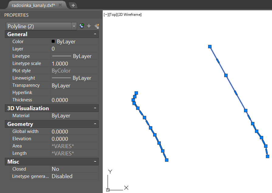
Fig. 111: Newly created *.dxf file containing two channel objects
Since the original files of the Radošinka stream (*.dwg and *.dxf) as well as the file of the new channels are prepared in the S-JTSK coordinate system, the new channels can be transferred to each of the original files by copying with the basic point (see chapter “S-JTSK coordinate system in the AutoCAD environment”), or by using external references after saving the new file in the *.dwg format and setting the correct units (metres) for both drawings (Fig. 112).
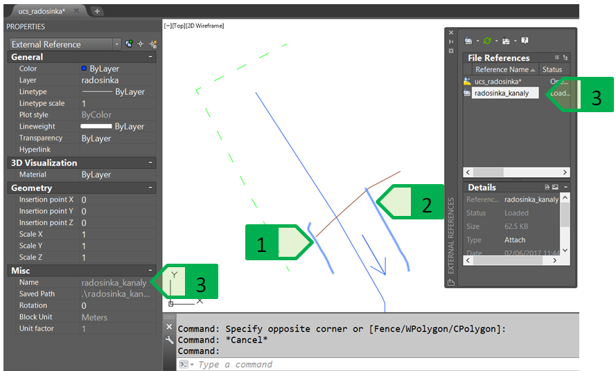
Fig. 112: Displaying the channels linked as an external reference to the situation file of the Radošinka stream, 1 - channel no. 1; 2 - channel no. 2; 3 - external reference of the *.dwg file of the channels
This trivial task explains the possibility of exporting data from the QGIS environment, but it should be noted that in this way it is possible to transfer any vector data that can also be generated as a result of more complex and complicated tasks such as determining the boundary of a river basin, finding a territory with a slope greater than that required value for the demarcation of the protective grassing or forestation, the import of contour vectors, and other tasks requiring the processing of the project documentation based on various GIS analyses, and their subsequent import into the CAD environment will allow these data to be used as a basis for the processing of the project documentation and preparation for the subsequent geodetic demarcation in the terrain.