External references
The main function of the external references is the use of multiple background documents and their management. A typical example is the work of multiple users on a single project, consisting of several drawings with different contents - a situation drawing where the proposed elements are gradually inserted, as well as the filling of the existing status data (additional geodetic measurements of the topography, drawing of the line routes, of the protection zones and so on) . The difference, compared with the combination of elements by inserting from another drawing, is that when changing the contents of an external reference drawing, this change is also reflected in the target drawing in which the external reference is inserted.
The use of external references will be explained in the drawing of the Radošinka stream (units: meters, drawing in S-JTSK). First, the drawing of the electric line (units: meters, drawing in S-JTSK) will be attached. Subsequently, two drawings will be added to the situation drawing of the pumping station - additional geodetic demarcation of the planimetry and the topography of the terrain (units: meters, drawing in S-JTSK) and the drawing of the pumping station floor plan (units: millimetres). Finally, the drawing of the access road to the pumping station (units: meters, drawing in S-JTSK) will be attached, to which the drawing of the bridge through the channel “C” will be attached (units: millimetres).
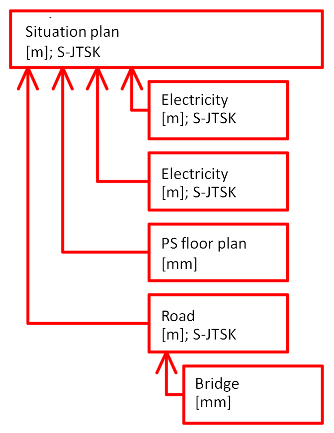
Fig. 16: Scheme of the attachment of the particular external references to the situation drawing of the pumping station
External references and units of the drawing
At work, for each drawing, it is necessary to correctly set the drawing units when inserting the content, which ensures the conversion of the dimensions between the drawings prepared in different units. With this setting, we ensure that, for example, a pumping station with the dimensions of 20,000 x 10,000 unit will represent a size of 20,000 x 10,000 millimetres, which will automatically be converted to 20 x 10 units when inserting this drawing as an external reference into the situation drawing prepared in metres, that is, 20 x 10 metres and not to the original 20,000 x 10,000 units, which would be 20,000 x 10,000 meters without setting the units in the situation drawing.
Attaching the external references
The attaching of the external references is done by using the command “ATTACH”, or the attachment is possible only using the pallet of external references that we can open on the “Pallets” panel on the “View” tab, or on the “Reference” panel on the “Insert” tab, or by using the command “XREF”, or “EXTERNALREFERENCES” (Fig. 17).
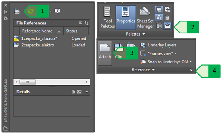
Fig. 17: Attachment of the external references to the drawing, 1 - attachment of the external references using a pallet of external references; 2 - opening the pallet of external references on the “Reference” panel on the “View” tab; 3 - attachment of the external references using the button ATTACH on the “Insert” tab on the “Reference” panel; 4 - opening the pallet of external references on the “Reference” panel on the “Insert” tab
The drawing of the electric line will be the first to be inserted. Since the units in both drawings are identical (meters), it is not necessary to perform the scale change - the scale in the axes x, y, z will remain to be set to (Fig. 18 - 1). The drawings of the situation as well as the electric lines are prepared S-JTSK and in metres, so they both have the same beginning of the coordinate system - the point with a coordinate [0,0,0], so we can use this point as an insertion point (Fig. 18 - 2). So the software inserts the external reference - the drawing of the electric line into the target drawing at a point with the coordinate [0,0,0] so that the basic insertion point of the external reference (by default, set to the point with the coordinate [0,0,0]), inserted at the coordinate [0.0.0] of the target drawing). The rotation angle remains at the value of “0” - it is not necessary to rotate the external reference because the situation and the drawing of the electric line display their contents in the real geodetic position in the S-JTSK coordinate system (Fig. 18 - 3).
When selecting the reference type (Fig. 18 - 4), there are two options:
- Attachment – the attached external reference becomes an attachment of the target drawing, if the entire target drawing is attached to the next drawing, the external reference attached to the target drawing will be attached, besides the design of the target drawing.
- Overlay – the attached external reference becomes only a background for the target drawing, if the entire target drawing is attached to the next drawing, only the design of the target drawing will be attached, without the external reference.
When selecting the access road, it is best to select a relative access road (Fig. 18 - 5), as it is possible, when moving the whole folder with the drawing and the external reference, to immediately display the reference, without having to re-search it and attach it - the program takes the partial hierarchy of the folders specified as a path (e.g. ..\Publikacie\Skripta_CAD\xref\2cerpacka_elektro.dwg ), it will start the search from the folder higher than the home directory of the drawing, and then it follows the specified directory structure). Other path types are a full path - Full path (written if the whole path to an external reference file, e.g. D:\Publikacie\Skripta_CAD\xref\2cerpacka_elektro.dwg) or no path - No Path (the program will search for an external reference file in the default browse of the folders).
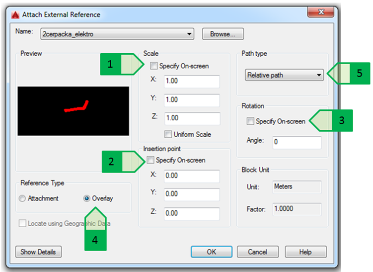
Fig. 18: Window for the attachment of an external reference. 1 - insertion scale; 2- insertion point; 3 - rotation angle; 4 - reference type; 5 - path type
The attached external reference is then displayed in the drawing. By default, the colour of external reference objects is displayed in reduced tones (Fig. 19), making them relatively easy to visually distinguish from other objects - but this colour change does not occur when printing.
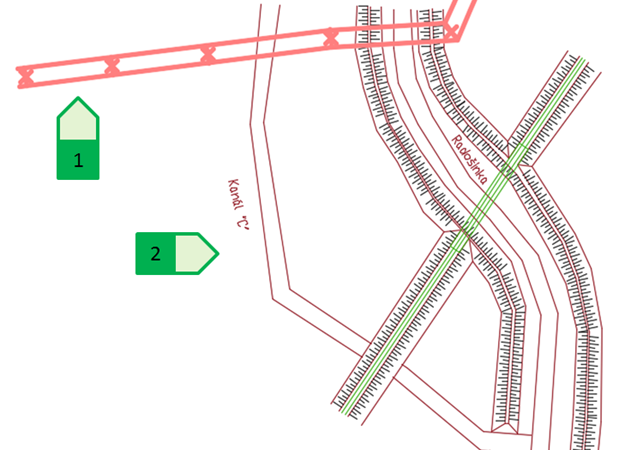
Fig. 19: External reference of the electric line inserted into the situation drawing. 1 - route of the electric line; 2 - objects of the situation drawing
The rate of the colour reduction is expressed in percentages from 0 to 90 (the default setting is 50), and it is determined by the variable “XDWGFADECTL”, which can be started using the command line and entering a new value or setting the colour reduction using the slider, or by entering the percentage value on the “Reference” panel on the “Insert” tab (Fig. 20).
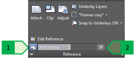
Fig. 20: Setting of the colour reduction of the external reference on the “Reference” panel on the “Insert” tab, 1 - using the slider; 2 - by entering a numerical value
Management of the external references
The basic tasks of the external reference management can be performed in the external reference palette and they include the following tasks:
- Unload - Unloads the linked reference so it will not be displayed but will not be removed from the drawing.
- Reload - Restores the linked reference after changing it in the drawing or reloads the released reference.
- Detach - Detaches the external reference and removes it from the drawing so it cannot be reloaded using the references management. The reference drawing is re-inserted if necessary, together with the setting of all parameters.
- Bind - The content of the external reference is moved into the target drawing, and the external reference is then detached. Any changes in the drawing of an external reference will no longer be displayed in the target drawing from that moment. The binding of the type “Bind” will ensure that the blocks in the drawing of an external reference are renamed in the format “name_of_external_reference“$n$“name_of_block”. The binding of the type “Insert” ensures that the blocks in the drawing of an external reference will have the same name as in the drawing of an external reference. If a block with the same name already exists in the target drawing, the block definition will be used automatically, and the new blocks from the external reference file will be inserted according to the block definition from the target drawing.
- Type of the external reference - Allows to specify whether the reference should behave as an Attachment or as an Overlay.
Displaying the changes in the external references
The changes in the drawing of an external reference occur after the drawing of an external reference has been saved and re-loaded in the target drawing without the need for deleting and re-adding the changed drawing of an external reference . This functionality will be shown in an example of adding results - points of the geodetic measurement of points at the watercourse near the pumping station.
The file containing the additionally measured topography points is prepared in S-JTSK and its units are meters, and it will be added to the situation drawing which already contains an external reference of the electric line (Fig. 21).
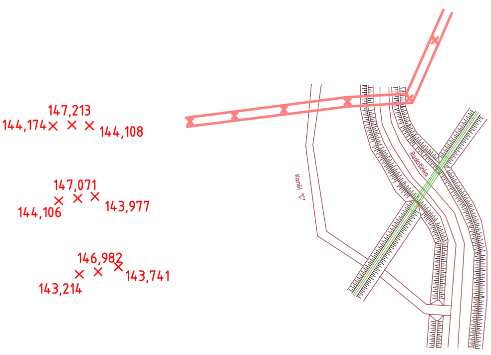
Fig. 21: Attachment of the external reference of the additionally measured points. Points in the drawing of the external reference of the additional measuring (on the left); display of the target situation drawing before attaching the additionally measured points (on the right).
The file containing the additionally measured points will be attached in the same way as when attaching the route of the electric line (it will be attached as an overlay external reference), so the additionally measured points will be displayed in the situation drawing (Fig. 22).
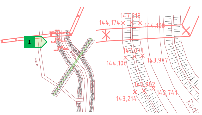
Fig. 22: Attached external reference. Situation drawing with the attached external reference of the additionally measured points (on the left); detail of the view of the attached external reference (on the right); 1 - additionally measured points.
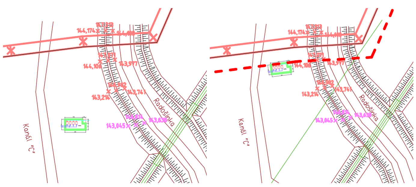
In practice, however, we encounter situations when, during the works in the particular drawings, some changes are made - for example, in the drawing of an external reference other additionally measured points are added to the additionally measured points (Fig. 23).
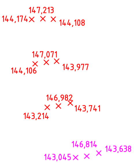
Fig. 23: Adding other points into the drawing of an external reference of the additionally measured points. Red points - original; purple points - added points.
If a change is made in the drawing of an external reference, and this drawing is saved, the program will automatically record the change and reports it in the target drawing by announcing it in the lower-right corner of the program as well as in the external reference palette (Fig. 24).
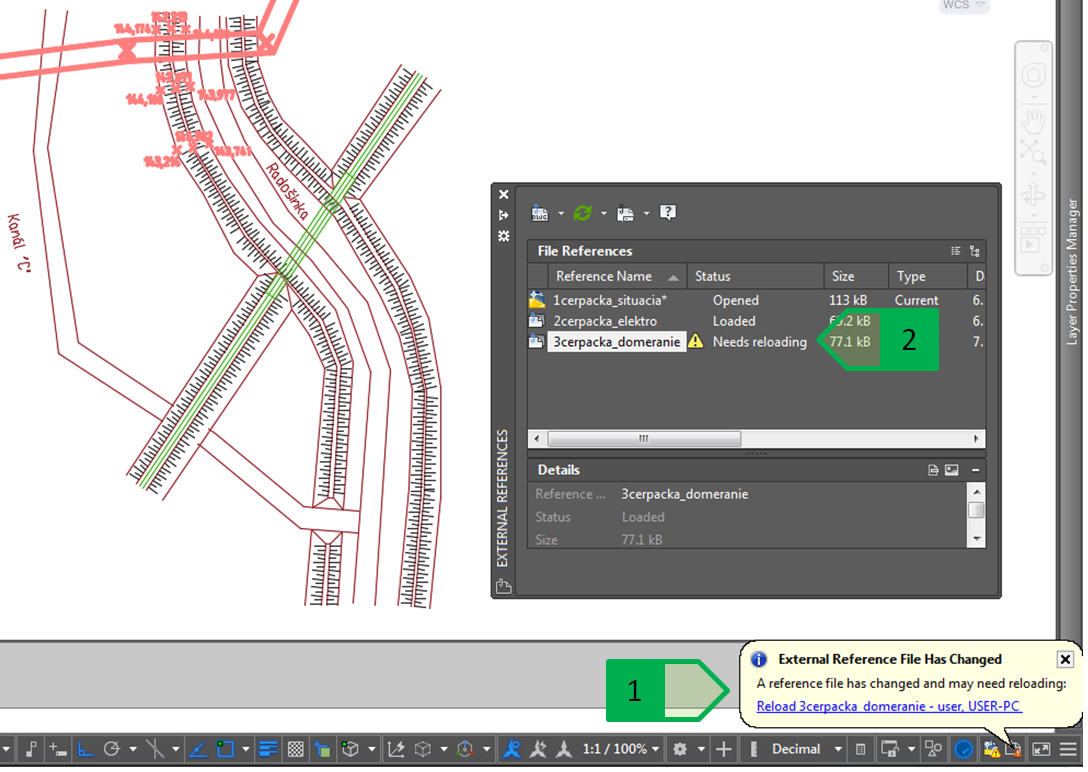
Fig. 24: Warning on the change in an external reference, 1 - warning in the program; 2 - warning in the reference table
By clicking on the announcement in the program, or by right-clicking on the changed external reference in the external reference palette and by selecting the “Reload” option, the changes to the external reference will also be displayed in the target drawing (Fig. 25).
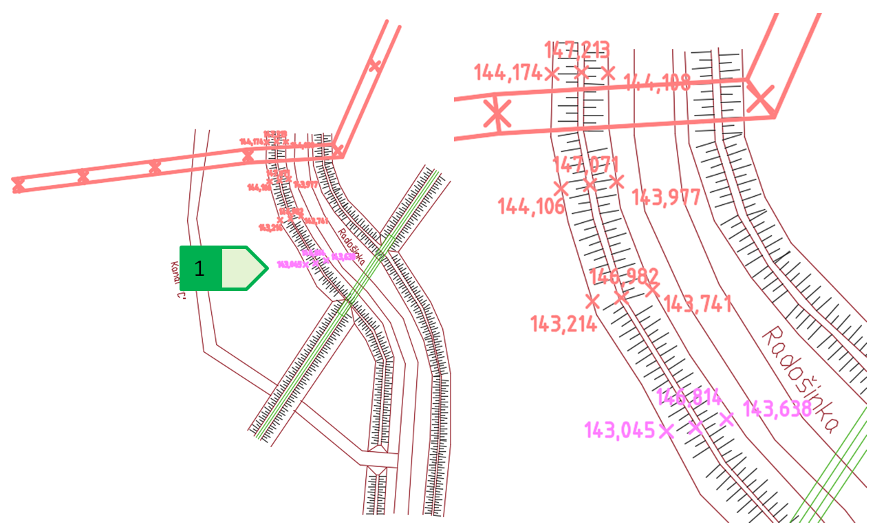
Fig. 25: Changed external reference. Display of the changed external reference (on the left), detail (on the right); 1 - added additionally measured points.
External references and units of the drawing
In case of combining the drawings prepared in different units, the software automatically re-calculates the dimensions. In case of the model example in question, the solution of this type of task will be demonstrated in the attachment of the external reference of the pumping station floor plan to the situation drawing - the situation drawing is prepared in S-JTSK and in meters, and the drawing of the floor plan is prepared in millimetres (Fig. 26).
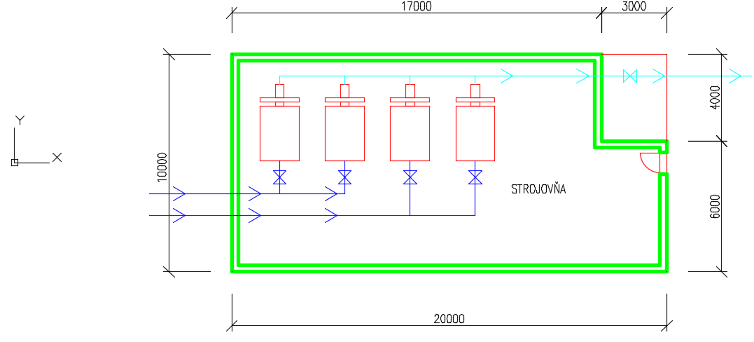
Fig. 26: Floor plan of the pumping station
Since the insertion point of the drawing of the floor plan is the point with the coordinate [0,0,0], and the situation design is located approximately at the coordinate [-503480, -1263250], it is better to insert an external reference at the point specified on the screen, so during the insertion of an external reference we select this option (Fig. 27) - another option is to leave the insertion on the point with the coordinate [0,0,0] and move the external reference using the command “MOVE”, or enter the exact coordinates in the target drawing.
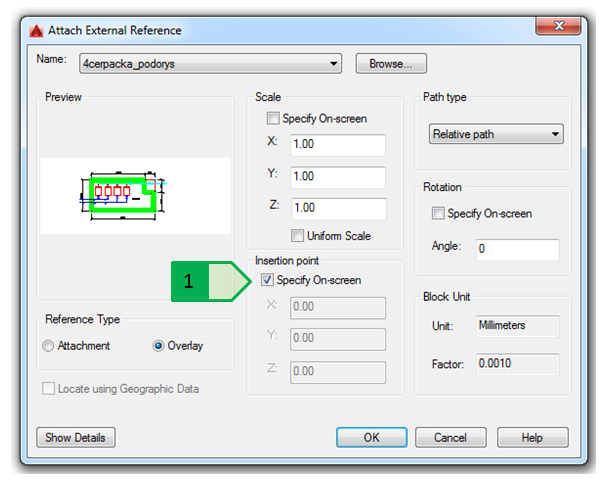
Fig. 27: Insertion of an external reference of the pumping station floor plan, 1 - setting the insertion point for the selection on the screen
After the attachment of the external reference into the target drawing (Fig. 28), it is possible to manipulate the external reference - rotate and move it into the requested position, while respecting the spacing distances mentioned in the previous chapter.
 0
0
Fig. 28: Placing the external reference on the point selected on the screen. Placing the external reference on the point selected on the screen (on the left) and moving it into the requested position (on the right).
Layers of the external references
By attaching the external references, the layers of the external reference are also loaded in the target drawing in the format “name of the external reference file|name of the layer in the external reference”. In case there is a layer with the same name in the drawing of an external reference as in the target drawing or another drawing attached as an external reference, a different layer will be used for each file (Fig. 29). The exceptions are the layers “0” and “Defpoints” that will always be listed together in the target drawing, regardless of whether there are objects in them in the target drawing or in the drawing of any attached external reference.
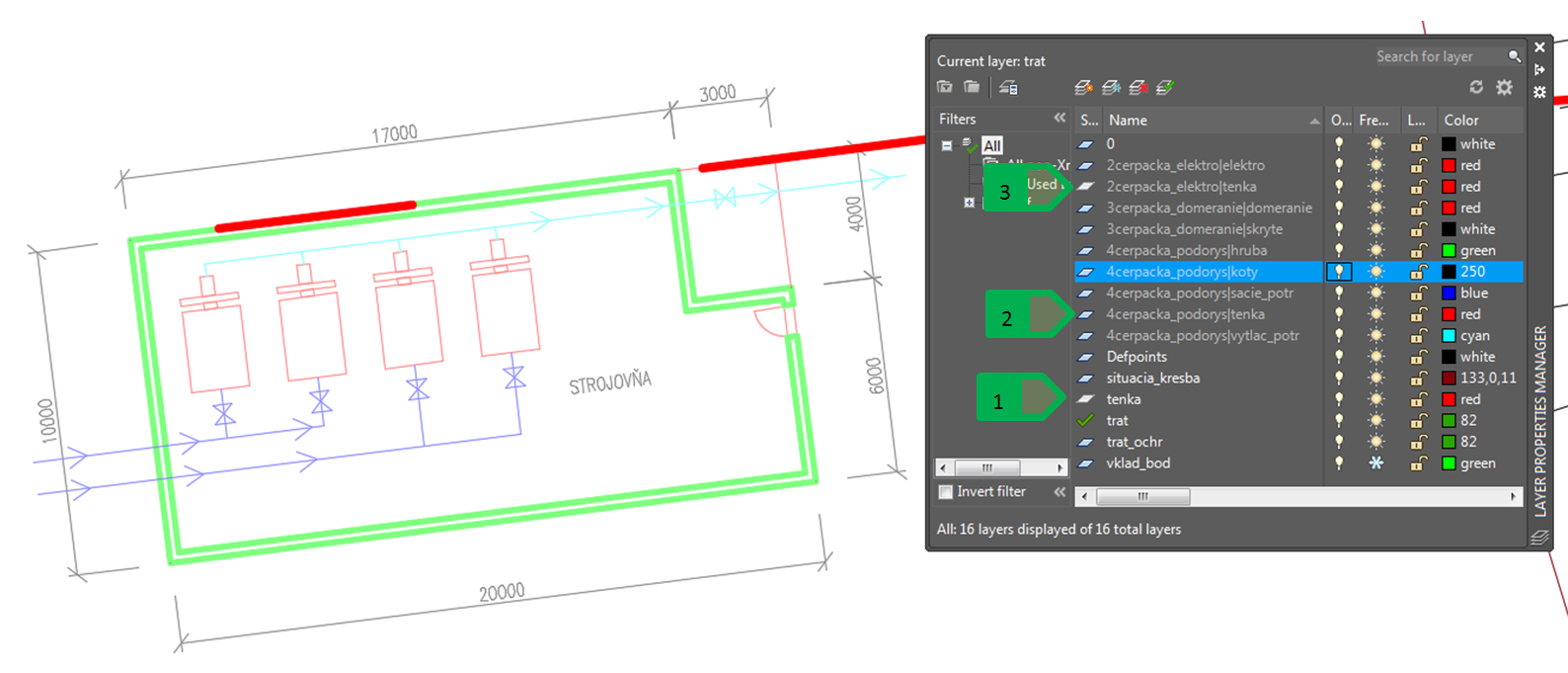
Fig. 29: Layers of the external references, 1 - “thin” layer in the target drawing; 2 - “thin” layer in the drawing of the pumping station floor plan; 3 - “thin” layer in the drawing of the route of the electric line
With the layers of the external references, it is then possible to manipulate the layers of the target drawing itself in the same way - to turn on/off, to freeze/unfreeze, unlock/lock, to change the colour, type and thickness of the line (Fig. 30).
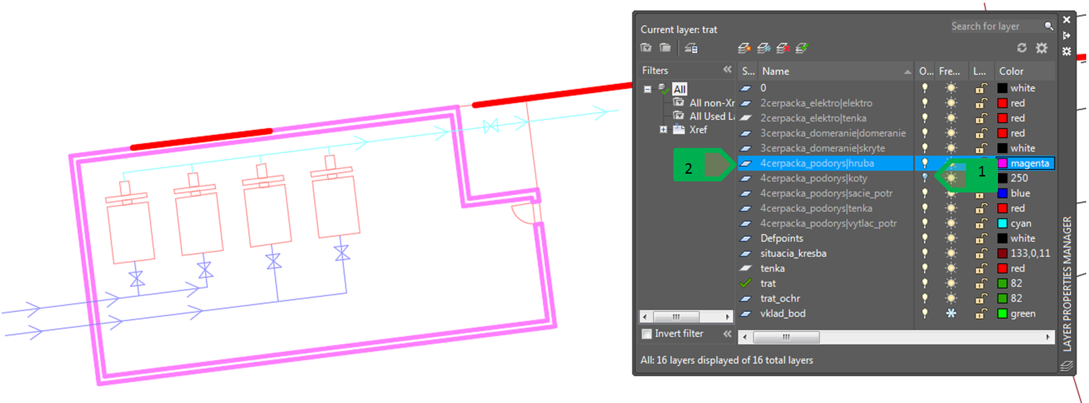
Fig. 30: Change to the properties of the layers of the external references, 1 - turning off the “dimension” layer; 2 - change to the colour of the “thick” layer from green to purple
The changes to the layer settings made in the drawing of the external reference itself will not appear in the drawing, but the creation of a new layer will appear - after reloading the external reference, the layer and the objects in it will appear in the target drawing.
Setting the base point of the drawing
The beginning of the current coordinate system of the drawing is set as the base point of each drawing - the point with the coordinate [0,0,0]. To change the basic point of a drawing, use the command “BASE” and select its new location with the cursor or by entering the numeric value of the coordinates. When inserting an external reference of the drawing, the content of this drawing will be inserted so that the basic insertion point of the drawing of the external reference will be the same as the insertion point of the target drawing that we specify when attaching the external reference (Fig. 18 or Fig. 27).
The practical use of the basic point setting will be explained in the example of the bridge above the “C” channel. First, an external reference for the outline of the spatial relations of the place where the road crosses the “C” channel is inserted into the drawing of the road - both drawings prepared in S-JTSK have the basic point in the coordinate [0,0]. The situation drawing will be attached as an external reference of the “Overlay” type. Subsequently, the external reference of the bridge, which is prepared in millimetres (the basic point is in the coordinate [0,0]), is added into the drawing of the road and it is inserted on the pre-prepared point (Fig. 31). When selecting an external reference type, the “Attachment” option is selected - when attaching the drawing of the road to the situation drawing, this setting will allow the drawing of the bridge to be automatically attached to the situation drawing as a separate external reference. The correctly set drawing units ensure the conversion, or change of the scale of the external reference to the units of the target drawing, which means that the external reference - the drawing of the bridge (drawn in millimetres), with the dimensions of 17,000 (mm) x 11,000 (mm), is displayed as an object with the dimensions of 17.0 (m) x 11.0 (m) in the target drawing of the road (prepared in meters in S-JTSK).
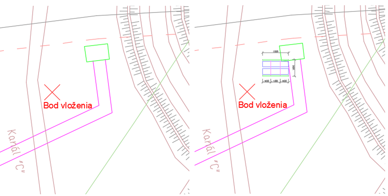
Fig. 31: Drawing of the road with the attached external reference of the situation (on the left), attachment of the drawing of the road (on the right)
If it is necessary to change the basic insertion point in the drawing of the bridge, the command “BASE” is used and the new basic insertion point is selected by the cursor or by entering its coordinates. After reloading the external reference in the target drawing, the design of the external reference is displayed, taking into account the changed basic insertion point (Fig. 32).
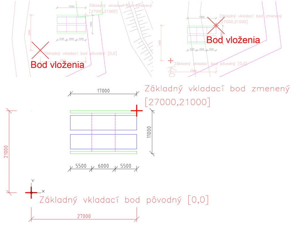
Fig. 32: Change of the basic insertion point. original basic point (at the top on the left); changed insertion point (top right); displaying the change of the setting of the basic insertion point in the drawing of the bridge (at bottom).
External reference of the “Attachment” type
By using the external reference of the “Attachment” type, it is ensured that if we attach a drawing with an attached external reference of the “Attachment” type, this external reference will be attached with the drawing (Fig. 33).
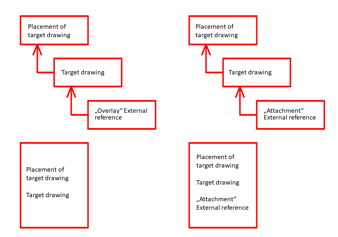
Fig. 33: Difference between the attachment of the external reference of the “Overlay” type (on the left) and the “Attachment” type (on the right)
In case of the bridge above the “C” channel this means that the drawing of the road, which includes the drawing of the bridge as the external reference of the “Attachment” type, will be attached to the drawing of the bridge when attaching the drawing of the road to the situation drawing (Fig. 34).