Working with the blocks
Working with the blocks will be explained in two drawings:
- in the first drawing, we create a block showing the floor plan of the sewer hatch,
- in the second drawing, the solution of the sewer system in the new part of the municipality Veľký Lapáš is prepared where the sewer hatch block will be used.
Creating the block
The principle of creating, modifying, and using blocks will be explained in the creation of a sewer hatch block. It is given that the sewer hatch is of a circular shape with a diameter of 600 mm and there are two circumferential holes in it for locking with a diameter of 20 mm (Fig. 35).
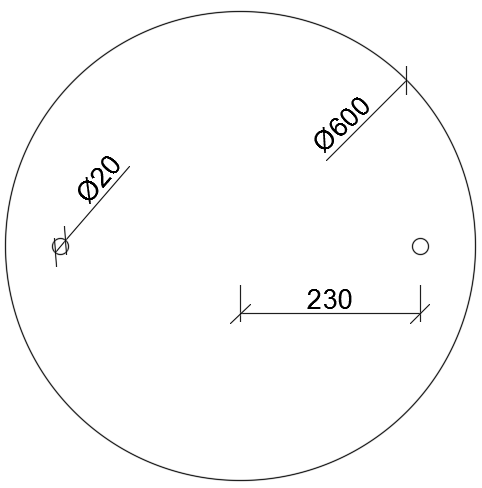
Fig. 35: Layout of the sewer hatch with a diameter of 600 mm
In the new drawing, therefore, we will create this basic design without dimensions, the drawing units will be millimetres - the design will be created as three separate circles with the required dimensions in the “thin” layer, which we will also create in the new drawing. From this created drawing (Fig. 36), we then create a block named “hatch”.
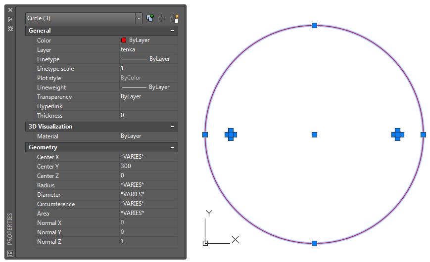
Fig. 36: Design of the hatch created from three circles
You can start the creation of the block by using the command “BLOCK” or by using the icon on the “Block” panel on the “Home” tab, or on the “Block Definition” panel on the “Insert” tab (Fig. 37).
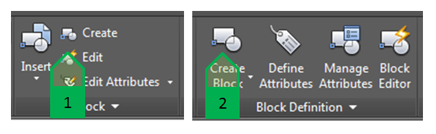
Fig. 37: Using the command for block creation. 1 - icon from the “Home” tab; 2 - icon from the “Insert” tab
When we use this command, a dialogue window (Fig. 38), is opened we you can set the parameters of the new block. When creating the block, enter the following parameters:
1. “Name” - the name of the block that will be unique in the drawing,
2. “Base Point” - the insertion point - enter it using the selection on the screen or as the coordinates of the drawing;
3. “Block Unit” - the units of the block - by default, the program automatically offers the units of the drawing,
4. “Hyperlink” - the link that opens when you click on the block (Ctrl + clicking with the left button of the mouse),
5. “Objects” - the objects for the creation of a block - define the objects for the creation and select what happens to the selected objects in the drawing. We can select one of the three options:
a. to leave the objects as separate blocks and to create a block,
b. to convert the objects to a block, to remove them and to replace them with the created block,
c. to convert the objects to a block and to remove them.
6. “Behaviour” - the behaviour of the block - we can select from the following options that we can combine:
a. Annotative block
b. Unified scale of the block of all three axes
c. Enable block layout
7. “Description” - the description of the block - it is used to describe the block, the description is displayed in the Design Center (Fig. 47)
8. “Open in block editor” - the setting whether the block should be opened immediately in the block editor
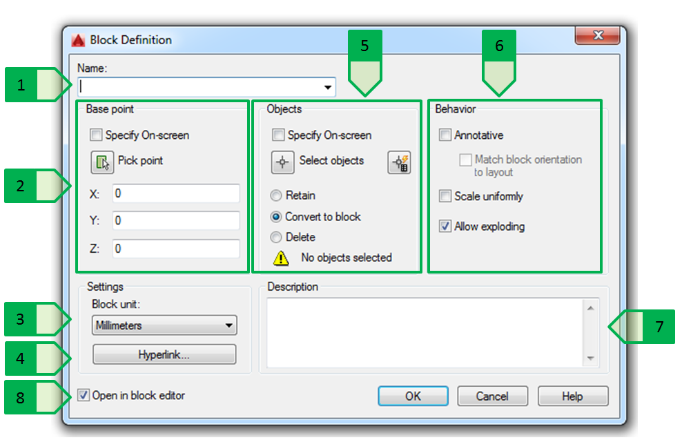
Fig. 38: Dialogue window to create a new block, 1 - name; 2 - insertion point; 3 - units; 4 - hyperlink; 5 - objects; 6 - behaviour of the block; 7 - description; 8 - automatic opening in the block editor
For the sewer hatch, set the following parameters (Fig. 39):
1. name of the block - “hatch”
2. insertion block - centre of the hatch circle
3. units - millimetres
4. hyperlink – do not enter
5. objects - three circles forming the design of the sewer hatch, converts the objects and removes them
6. behaviour of the block - Unified scale of the block and Enable layout
7. description - “Circular hatch, diameter 600 mm”
8. to cancel the automatic opening in the block editor
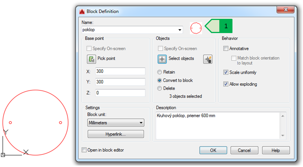
Fig. 39: Creation of the hatch block from the selected objects, 1 - block preview
The created block will be displayed in the drawing inserted into the original location, but the original objects (three circles) will no longer be in the drawing. By copying this block to different locations in the drawing, the individual blocks will be displayed in multiple locations. When selecting a particular block, the parameters of the particular selected block - name, location, units , and others are displayed in the property palette (Fig. 40).
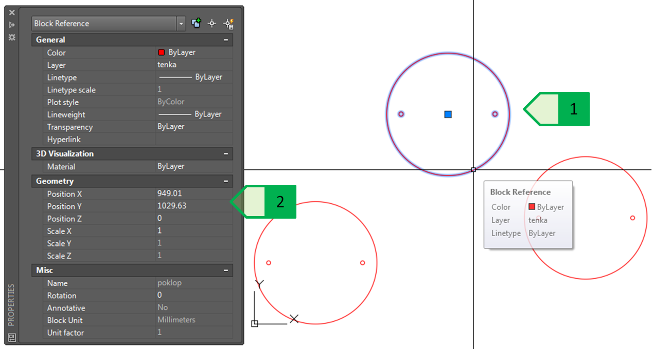
Fig. 40: Multiple insertion of a block in the drawing, 1 - selected block; 2 - properties of the selected block
Modification of the block
If we need to change the definition of the block (modification, removal or adding of objects into the design of the block), and so that this change is reflected in each copy of the block in the given drawing, it is necessary to modify the block in the block editor that is started either by double-clicking the selected block or by clicking the right button and selecting the “Block editor” option in the local menu (but only one copy of this block can be marked, nothing else), or by using the icon on the “Block” panel on the “Home” tab or on the “Block Definition” panel on the “Insert” tab which opens the block editor, or the window for the selection of the block to be edited (Fig. 41).
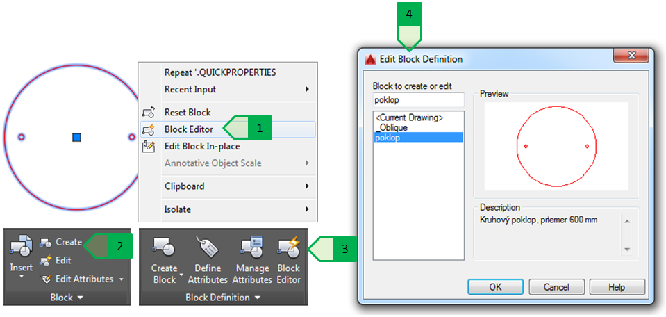
Fig. 41: Starting the block editor, 1 - selection from the local menu; 2 - icon from the “Home” tab; 3 - icon from the “Insert” tab; 4 - window for the selection of the block to be edited
When you open the block editor, a new “Block Editor” tab will appear, containing various tools fro block editing. In addition, a new “Close” panel appears on each tab to end the block editing. In the block editor, the necessary modifications are made - in case of the sewer hatch, the hatch diameter description and the handle display for handling the hatch are added. Subsequently, the block editor closes and changes in the block are saved (Fig. 42).
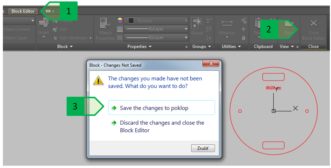
Fig. 42: Saving the changes in the block editor, 1 - “Block editor” tab; 2 - “Close” panel to end the block editing; 3 - saving the changes in the edited block
Saving the changes of the block definition ensures that all copies of the block inserted into the drawing change without changing each block separately (Fig. 43).
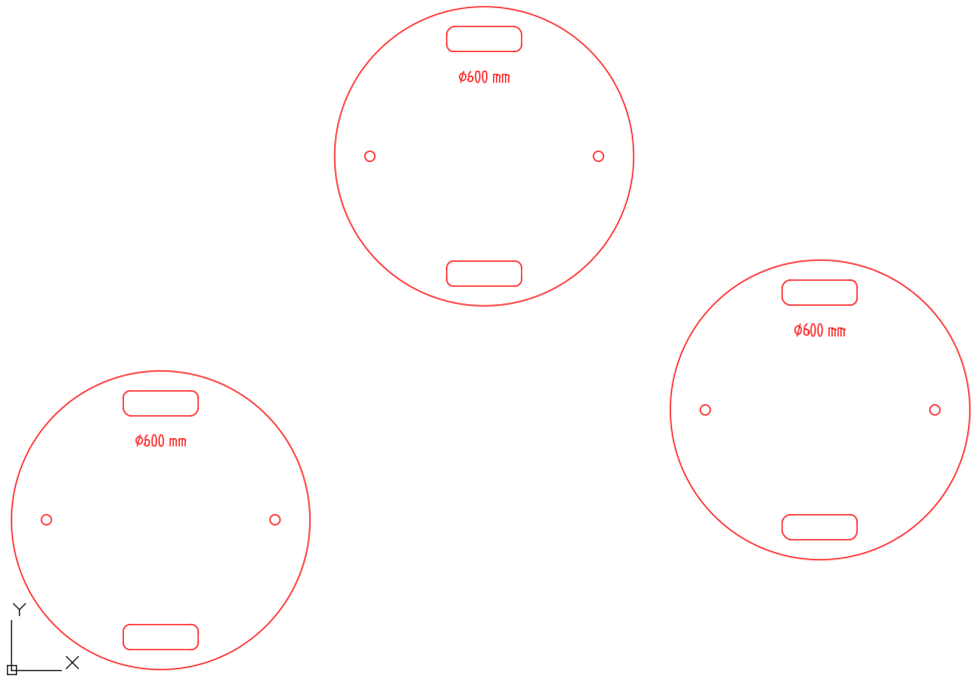
Fig. 43: Displaying the change of the block definition
However, each block copy can be changed individually as required in terms of placement, rotation, and insertion scale, independently of other block copies in the drawing (Fig. 44).
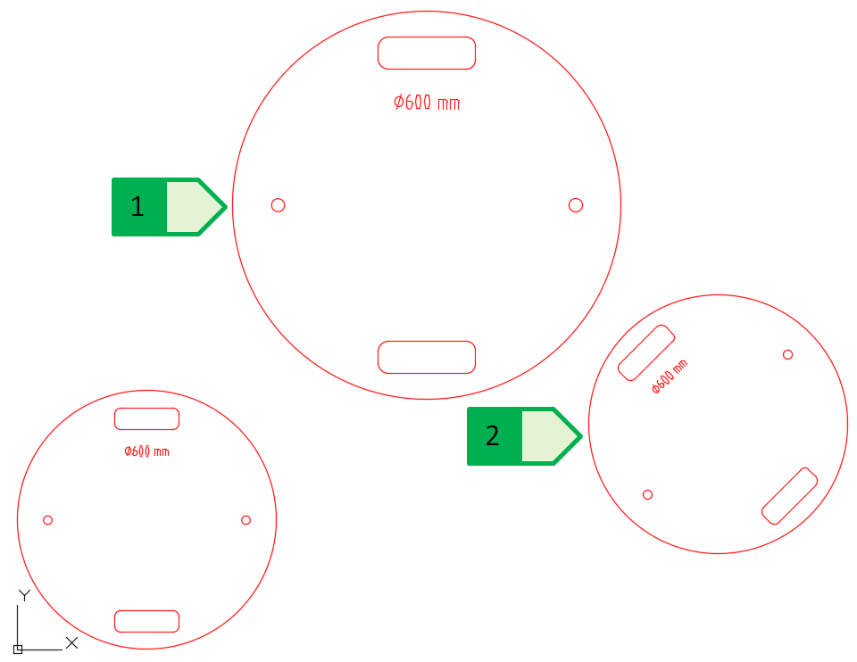
Fig. 44: Changes of the particular block copies, 1 - block scale changed to 1.5; 2 - rotation angle of the block changed to 45°
Using blocks in multiple drawings
The created blocks can be copied between drawings, or added from the different drawings to the required drawing. If the units of blocks, or of the target drawings are set correctly, the program automatically re-calculates the drawing dimensions - as with external references.
The simplest way is to copy the block into the clipboard, or copy the block into the clipboard through a reference point and then insert it into the target drawing.
In case of a file with the sewer hatch block with the name “hatch”, first (rotation angle 0°; scale 1.0) copy this block into the clipboard through a reference point using the command “COPYBASE” or the shortcut Ctrl + Shift + C. Use the insertion point - centre of the hatch circle as the reference point. Then go into the situation drawing of the sewer system in the municipality Veľký Lapáš where we insert this block using the command “PASTECLIP” or the shortcut Ctrl + V to the first placement - the connection point of the sewer system branches (Fig. 45).
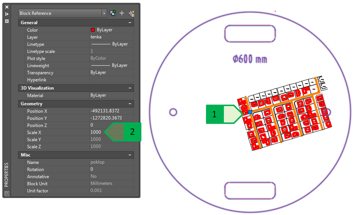
Fig. 45: Inserting the block “hatch” into the situation drawing of the sewer system, 1 - insertion point; 2 - scale of the inserted point
The block inserted into the situation design had a scale of 1.0 in the block drawing, but after inserting it into the situation drawing, the scale of the inserted block scale was changed to 1,000. This change was performed because the software automatically converted the scale so that the object - a block with a diameter of 600 units (or 600 mm) had the same dimension also in the target drawing. But this means that in the situation drawing we also have the dimension 600 units and therefore 600 m - the scale must be 1,000 times the original scale. After changing the scale on the property panel to 1.0, the block diameter changes to 0.6 units, i.e. 0.6 m (or 600 mm) to ensure the correct size of the block display prepared in millimetres in the drawing prepared in meters (Fig. 46). This modified block can be copied in the situation drawing without the need to adjust the scale using the command “COPY”, as the copying in the drawing keeps the parameters of the copied block.
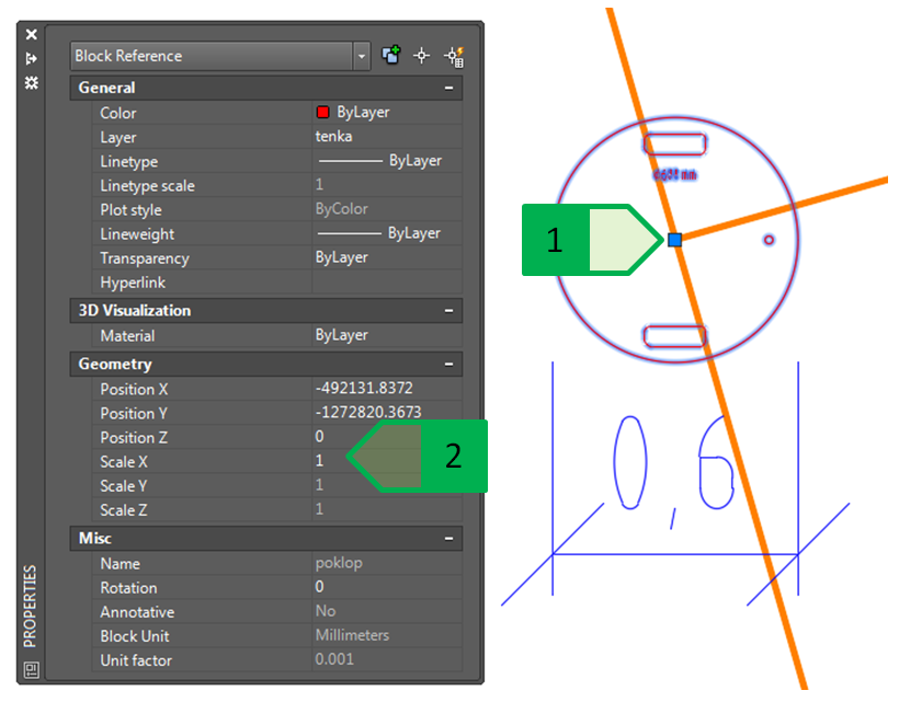
Fig. 46: Correctly modified scale of the block, 1 - scale of 1.0; 2 - insertion point of the block
Another option for inserting a block from one drawing into another is to use the “Design Center” palette, which can be turned on using the command “ADCENTER” or by using the “Palettes” icon on the “View” tab (Fig. 47).
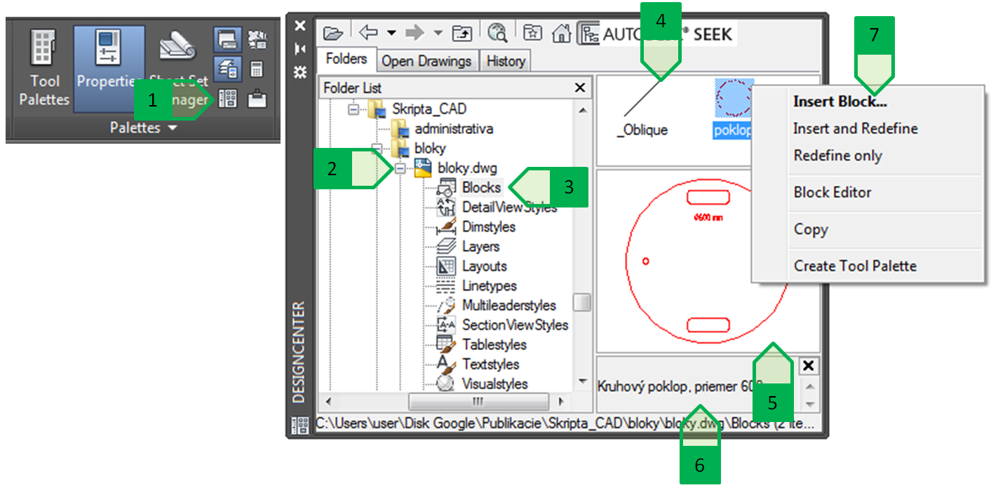
Fig. 47: “Design center” palette, 1 - icon to turn on the “Design center” palette on the “Pallets” panel on the “View” tab; 2 - selection of the required file from which the objects will be moved; 3 - selection of the object type to be moved; 4 - window of displaying objects of the selected type in the drawing; 5 - preview of the selected object; 6 - description of the block; 7 - local menu for manipulation with the selected block, opened by clicking the right button of the mouse
The required block can be added into the target drawing using the “Design center” palette in several ways:
- by clicking and dragging a block from the display window of each object (the block is inserted in the place selected by the cursor by placing the insertion point);
- by selecting “Insert Block ...” from the local menu for the manipulation with the selected block,
- by selecting “Copy” from the local menu for the manipulation of the selected block - the block will be copied into the clipboard by dragging the block using the reference point of the block.
When inserting a block using “Design center”, the block will be inserted automatically with a scale set to 1.0. With correctly set units, the sewer hatch will have a diameter of 0.6 m.
Subsequently, the given block of the sewer hatch is inserted into all areas where it is necessary to place the sewer shaft at all points of the connection of the individual branches, the slope or route direction change and in the distance up to 50 m between the particular shafts.
If we insert a new block into the target drawing that has the same name as the block that is already defined in the target drawing, the program inserts the block that has already been defined and not the block that we want to insert.
This situation will be explained in a practical example of the sewer system situation in Veľký Lapáš. The block of the circular hatch with the name “hatch” from the first file was inserted into the situation drawing - it is the hatch that will be placed in the road and it is a through road. In the next file, a hatch block, that is not a through hatch, was created, it has the shape of a square with the dimensions of 600 x 600 mm and is also named “hatch” (Fig. 48).
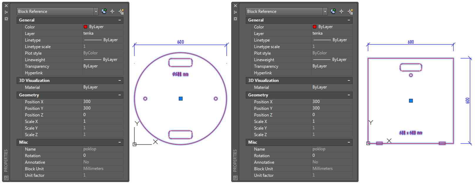
Fig. 48: Two different blocks with the same name. Circular hatch (on the left); square hatch (on the right).
When inserting a block of a square hatch into the situation drawing, this is the case that we insert a block named “hatch” which is created in the second drawing as a square hatch, but on the layer of the blocks of the situation drawing the block “hatch” is defined as a circular one - therefore, when inserting the block of a square hatch, the circular block is inserted.
To eliminate this problem, it is therefore appropriate that the naming of the blocks with different definitions is always original: in case of the sewer hatches, there the block of the circular hatch should be named, for example, “circular_hatch”, and the block of the square hatch should be named, for example, “square_hatch”- in this case it is possible to use both blocks in one drawing, as the names do not match.
The naming of the blocks must be solved in al drawings, we can use the command “RENAME” which opens a dialogue window for renaming the named objects, such as blocks, layers, dimension styles, and others (Fig. 49).
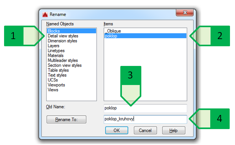
Fig. 49: Window for renaming the objects, 1 - list of types of the named objects; 2 - particular objects of the selected type in the current drawing; 3 - old name of the selected object; 4 - new name of the selected object
After correct renaming, it is possible to insert the block of the square hatch into the situation drawing, and to use the block of the square as well as the circular hatch, and place them as needed. (Fig. 50).
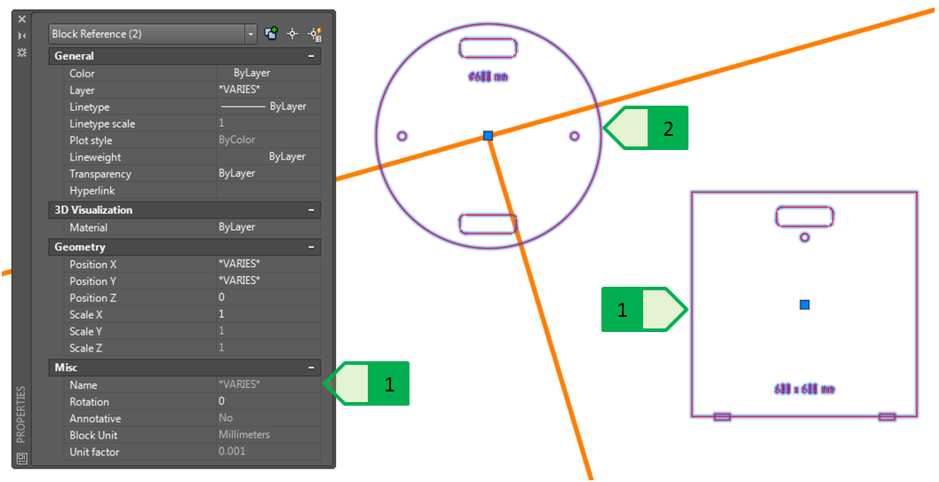
Fig. 50: Use of two hatch blocks in one drawing, 1 - name of the blocks is different; 2 - block “circular_hatch”; 3 - block “square_hatch”
Change of the block definition
Changing the block definition, i.e. the design - the individual objects that make up a block, is possible either by modifying a block in the block editor or by redefining a block using “Design center” (only for blocks with the same name).
The use of “Design center” for redefining a block is especially important when we have created a new definition for the block that we want to use for the re-definition of the existing block.
In case of the sewer system in Veľký Lapáš, we have a block of a circular hatch named “circular_hatch” inserted into the drawing, and we have, from the selected supplier, a drawing with the precise solution of the hatch block - this block is named “hatch_circle_600_alloy”. The drawing of the block from the supplier is prepared in millimetres, much like this block, and for both blocks, the centre of the hatch profile is selected as the insertion point (Fig. 51).
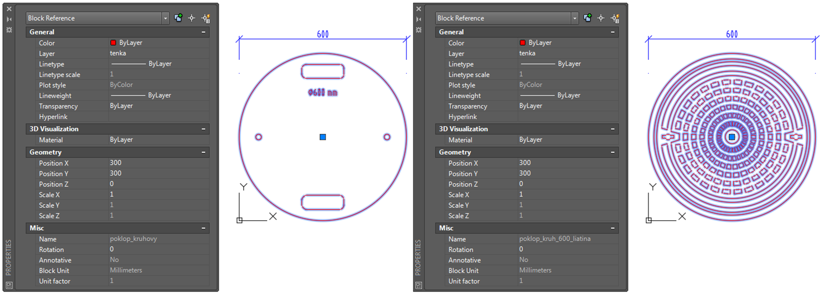
Fig. 51: Comparison of two blocks of the circular hatch. Original schematic block (on the left); new detailed block from the supplier (on the right).
If we insert the detailed block from the hatch supplier into the situation drawing, the inserted copies of the schematic block are not re-defined, only the third block will be inserted (Fig. 52).
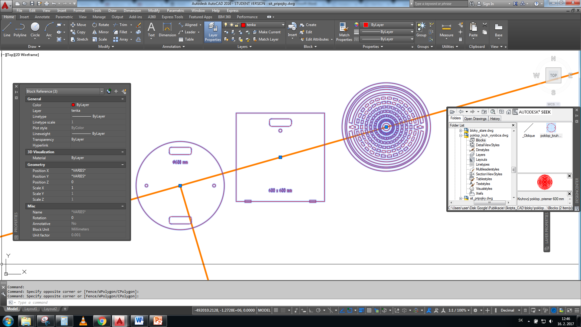
Fig. 52: Insertion of the detailed block into the situation drawing
The change of all inserted blocks of the circular hatches by re-defining them for the design of the detailed circular hatch requires first the renaming of the block “hatch_circle_600_alloy” to the name “hatch_circular” in the source drawing of this block and then, using “Design center”, it is only possible to re-define all the blocks or to re-define all the blocks and insert another copy of this block (Fig. 53).
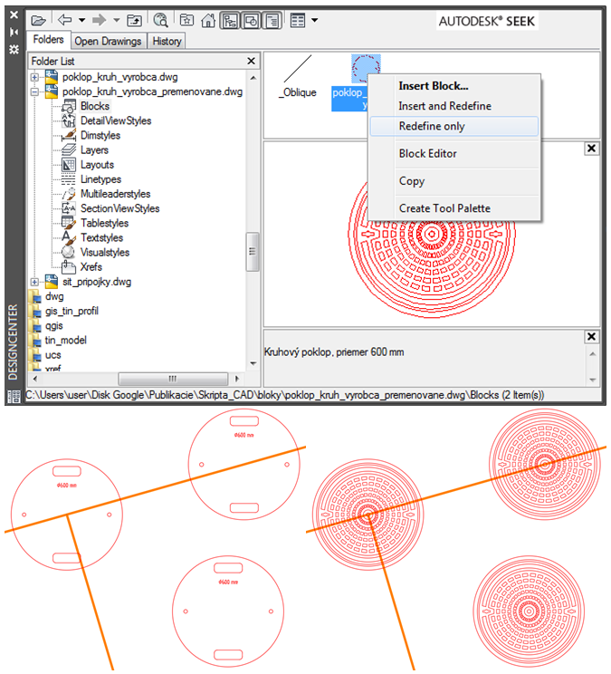
Fig. 53: Using “Design centre” for the re-definition of the block (at the top); original blocks (at the bottom on the left); re-defined blocks (at the bottom on the right)
Blocks with attributes
The text used in the block definition remains the same for each inserted block, so any change of the text in the block definition occurs in all inserted blocks. In practice, however, there are cases when it is necessary for the block to contain a text element that can be modified as needed, separately for each inserted block. In these cases, a text object is not inserted into the block definition, but an attribute is defined for the object - a text object rewritable for each block that is inserted separately and independently of the other inserted blocks. The attribute can be defined for each block from separate objects before the block is created, or the attribute can be defined in the block editor in the already created block.
Defining the attribute will be demonstrated in the block of the circular hatch to which the attribute - the number of the shaft over which the block is located - will be added. In the block editor, the required block of the circular hatch is opened. The definition of the attribute is done by using the “Define Attribute” tool on the “insert” tab on the “Block Definition” panel, or by using the command “ATTDEF” in the command line. In the block editor, the attribute can also be defined using the “Block Editor” tab and the “Action Parameters” panel using the “Attribute Definition” tool.(Fig. 54).

Fig. 54: Definition of the new attribute, 1 - defining using the “Insert” tab; 2 - defining using the “Block editor” tab available only in the block editor; 3 - mode; 4 - parameters; 5 - insertion point; 6 - text properties
The definition of the attribute is done in the dialogue window (Fig. 54) in which the properties of the attribute are set:
- Mode (Fig. 54 - 3):
• Invisible - value of the attribute which is not displayed and printed,
• Constant - value of the attribute which is an invariable constant,
• Verify - during the insertion of the block, the user is prompted to verify the accuracy of the value of the attribute,
• Preset - sets the value of the attribute to the pre-defined one without prompting the entering of the value,
• Lock Position - locks the position of the attribute, the attribute cannot be moved,
• Multiple Lines - allow the creation of a multi-line text for the attribute.
- Parameters (Fig. 54 - 4):
• Tag - tag of the attribute, cannot contain a space,
• Prompt - prompt displayed during the insertion of the block. If the field of prompt is not filled in, the tag (Tag) of the attribute will be used as the prompt. The prompt is not displayed when you copy the block already inserted in the drawing, but only when you insert the block (for example, using the command “INSERT” or using the “Design center” palette).
• Default - predefined value of the attribute. This field does not need to be filled in.
• Insert Field - allows entering the predefined value as a field - interactive value varies depending on the selected type (see chapter “Fields”).
- Insertion point (Fig. 54 - 5): allows to enter the placement of the attribute in the block,
- Text properties (Fig. 54 - 6): allows entering the drag point of the text, its style, height and rotation angle of the attribute text.
For the block of the circular hatch inserted in the situation drawing, we define a new attribute of the hatch number named “c_shafts” in the block editor so that its location can be moved as needed, when inserting the block, you will be prompted “Enter the shaft number” and the predefined value of the attribute will be “000”. The height of the text will be 200 - at a scale of 1:100, the height of the text of this attribute will be 2 mm after the creation of the output, and the drag point will be “left” - left bottom corner of the text line (Fig. 55).
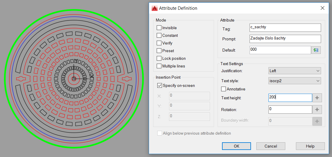
Fig. 55: Defining the attribute of the shaft number for the circular hatch
The attribute defined in this way will not be displayed in the already inserted blocks, and it cannot be edited because, during the insertion, the block did not have a defined attribute. The existing blocks must therefore be synchronized with the changed block definition. The synchronization is done using the command “ATTSYNC” or by using the button “Synchronize” on the “Block Definition” palette on the “Insert” tab (Fig. 56).
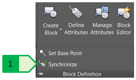
Fig. 56: Synchronization of the block attributes, 1 - Button of the synchronization tool for the attributes of the selected blocks
After using the command, it is necessary to select which block will be synchronized - either by entering the block name in the command line or by selecting the block from the inserted blocks in the drawing. The synchronization then updates all the inserted blocks of that block name in the drawing. If the attribute has a pre-set value, this value is applied to all blocks (Fig. 57).
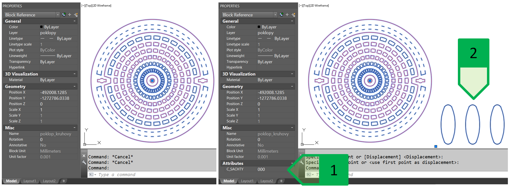
Fig. 57: Synchronization of the attributes. The block and its properties before the synchronization (on the left) and after the synchronization (on the right). 1 - displaying the attribute on the properties palette; 2 - displaying the attribute itself as a text in the drawing.
Thanks to the functionality of the attributes, for each inserted block it is possible to have the set attribute value independently of the other blocks. The modification of an attribute for the selected block is possible by rewriting it on the properties palette or acted double-clicking the selected block which opens the advanced attribute editor (Fig. 58).
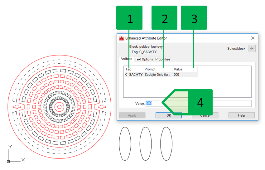
Fig. 58: Window of the advanced attribute editor, 1 - attribute tag; 2 - prompt to enter the attribute; 3 - current value of the attribute; 4 - field for the change of the attribute value
The block may have multiple unique attributes defined, each attribute may have a different mode. In the situation drawing of the networks, we create the markings block of the shaft type (Fig. 59) with three attributes:
- shaft type (direct, branch, junction of multiple sewers, ...) - visible attribute with locked position within a block,
- angle of the pipes - visible attribute with locked position within a block,
- supplier - not displayed and not printed attribute with locked position within a block.
The block created in this way can then be used to describe the particular shafts - each can have a unique combination of attributes and the information on the potential supplier will not be displayed - for example, in case of a public procurement, it is not possible to clearly define the supplier or the producer of materials, but, as the information for the project designer, it is advisable to keep this information.
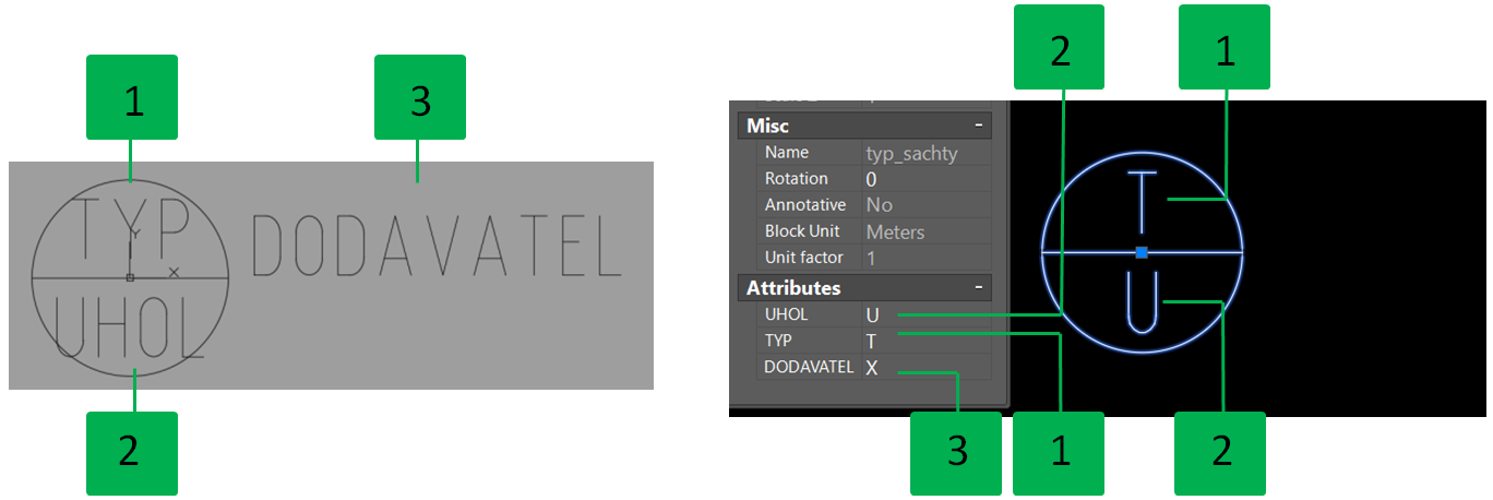
Fig. 59: Block of the shaft description. Displaying the attributes in the block editor with all visible attributes (on the left); Displaying the attributes in the drawing - the attribute of the supplier is not displayed in the drawing but it is possible to display and modify it in the properties palette of the block. 1 - attribute of the shaft type; 2 - attribute of the pipes angle; 3 - attribute of the supplier.
When selecting multiple blocks and modifying the attribute on the properties panel, the attributes of all selected blocks will change to the value specified on the properties panel (Fig. 60). This option is appropriate when multiple blocks require changing the value of the attribute to the same value - for example, for the marking blocks of items identifying the same type of shaft. In the example (Fig. 60) we see the change of the attributes of the marking for the shaft type (type “direct/180° to “branch/90°”).
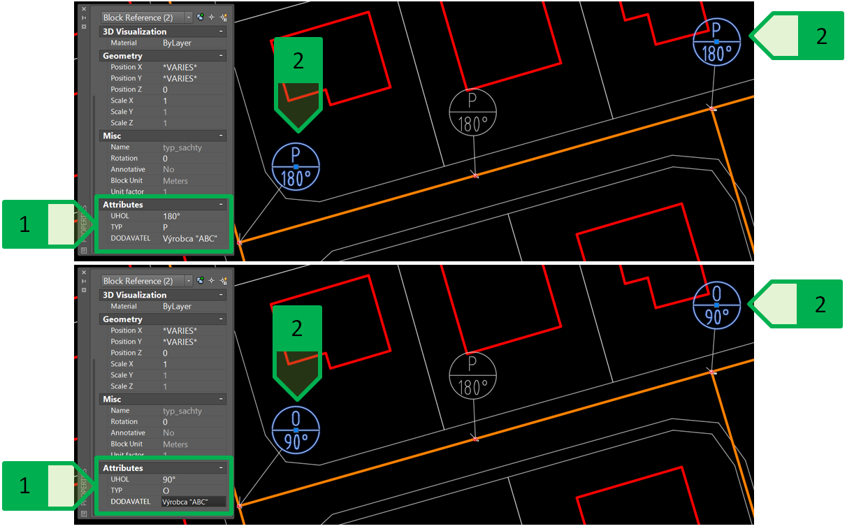

Fig. 60: Entering the same value of the attributes for multiple blocks using the properties palette. Blocks before the change of the attributes (at the top) and after the change of the attributes (at the bottom). 1 - values of the attribute for the selected blocks on the properties palette; 2 - selected blocks of the marking for the shaft type. Note: The attribute of the producer is not displayed in the drawing because it is in the “Invisible” mode.