Possibilities of linking CAD and MS Excel
Creating a link to the table
The existing program table in the *.xls file can be inserted into the drawing as an OLE-type object ( Object Linking and Embedding) by copying and pasting it with the usual shortcut Ctrl + C and Ctrl + V to ensure that the table is inserted into the drawing while maintaining the formatting according to the source - the table will have the parameters (formatting, content, dimensions, border, font, ...) as in the *.xls file from which the data are taken.
But the import of the table allows for the formatting and table contents of the drawing as well as the use of data for further calculations as well as the change of the data in the source file directly using the drawing.
The data import will be explained using the connections in Veľký Lapáš, where a table containing the production program of concrete sewer shafts will be attached to the drawing.
Before importing, first it is necessary to create the link of the drawing to the *.xls file using the data link manager (data link) that will be started by the “Data Link” tool on the “Linking & Extraction” panel on the “Insert” tab. In the “Data Link Manager” option, we create the new link and name it appropriately (Fig. 96).
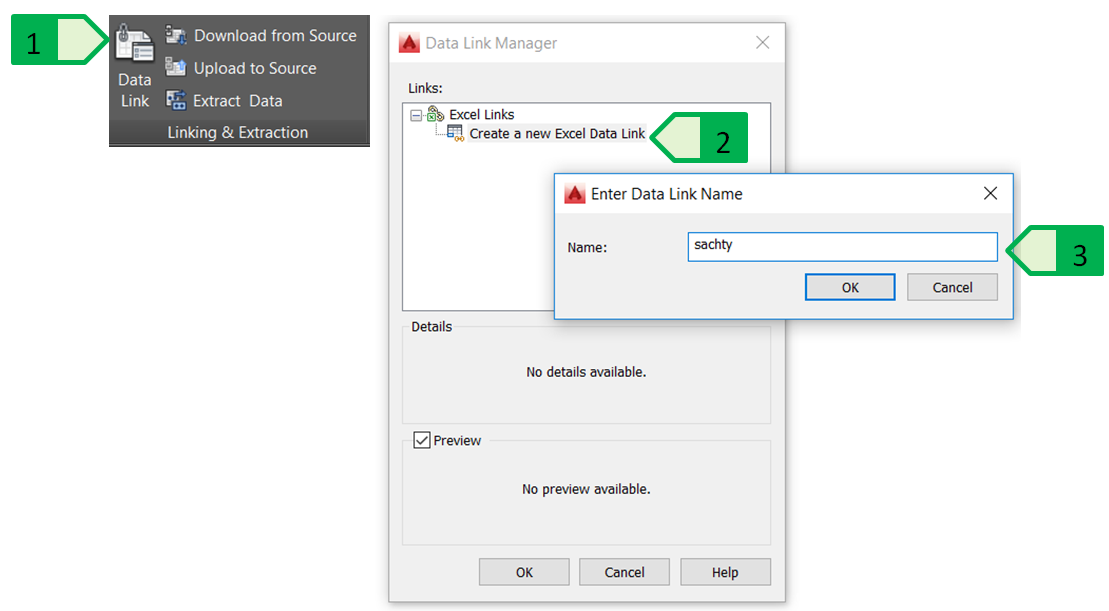
Fig. 96: Creating a new data link to the table, 1 - “Data Link” tool; 2 - creating a new link of the *.xls file and the current drawing; 3 - name of the new link
When creating a data link, it is necessary to define the parameters of this link (Fig. 97). The basic parameters include:
- location and type of path (relative, whole, no path) to the linked file,
- parameters of the linked file - sheet selection, link options (entire sheet, named range, defined range),
- cell content (retain the data format and formulas, retain the data format and use formulas in MS Excel, convert the data format to text and use formulas in MS Excel);
- enable writing into the source file - allows the *.xls file to be updated according to the changes made in the drawing table,
- cell formatting - use of MS Excel formatting and update it according to the formatting in the *.xls file, or start with the MS Excel formatting and do not update it later.
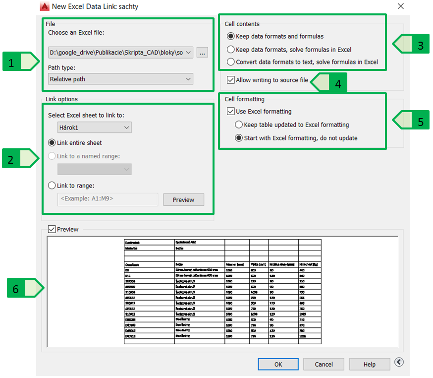
Fig. 97: Parameters of linking the file of the MS Excel program, 1 - file selection; 2 - parameters of the linked file; 3 - cell content; 4 - writing into the source file; 5 - cell formatting; 6 - preview of the currently linked content of the selected file
Inserting the table in the drawing
The created data link can then be used to insert a new table into the drawing, possibly reopening the data link manager for additional editing or creating a new data link (Fig. 98).
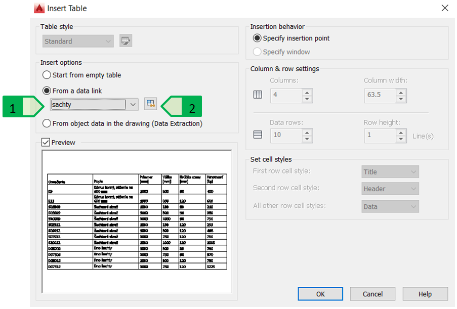
Fig. 98: Inserting a new table using the created data link to the file of the MS Excel program, 1 - data link selection; 2 - starting the data link manager
In the model example, the whole “Sheet1” from the “range.xlsx” table will be inserted, as the option to link the whole sheet was selected in the data link manager. After marking, the inserted table indicates the highlighted table corners in green colour that indicate the part of the table inserted as a data link to a file of the MS Excel program. The cursor will change when pointing to any of the linked cells - it displays the lock symbol (locked cell) and the chains (link to the contents of the MS Excel file) as the link of the MS Excel table creates a locked and linked table in the drawing (Fig. 99).
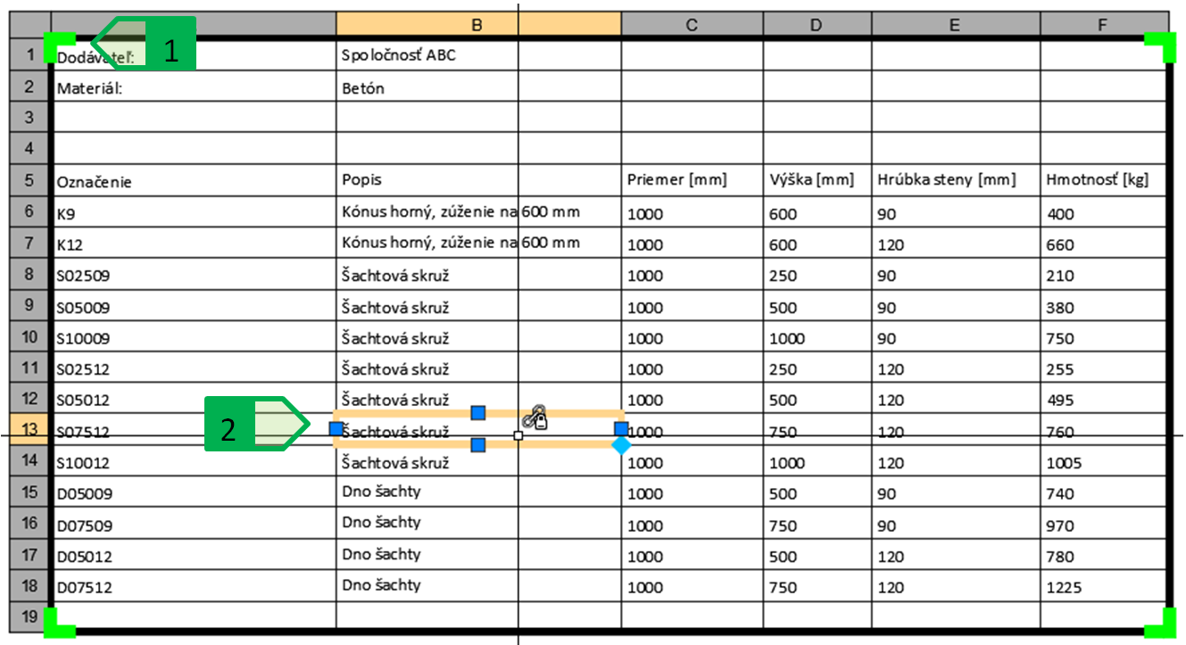
Fig. 99: Table of the range of concrete elements for the sewer shafts inserted into the drawing using the data link to the table of the MS Excel file. 1 - highlighted green corners of the table that indicate the part of the table linked using the data link; 2 - cursor indicating the cell that is locked and linked to the table file.
Editing the existing data link
In case we created a data link whose parameters are then have to be edited for objective reasons according to our requirements, it is possible to perform this modification also additionally or after inserting the table that refers to this data link.
In the example of inserting the table with the range of concrete elements from the “range.xlsx” file, several rows are inserted in the linked sheet too, which are not interesting for the drawing , as only the cells with the description of the columns and the data are required. For this purpose, it is not necessary to modify the source file of the table, but simply change the settings of the data link manager so that the given data link is not linked to the whole “Sheet1” but only to the range of cells we need to insert into the drawing, thanks to which the table already inserted into the drawing will be displayed in this modified setting (Fig. 100).
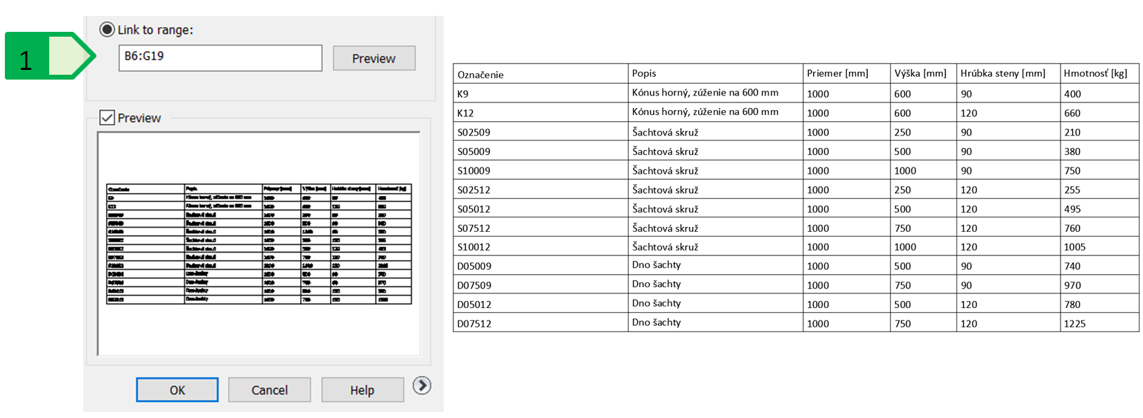
Fig. 100: Changing the created data link. Editing the range of the data link (on the left); Inserted table after the change of the data link (on the right); 1 - setting the range of the data link.
Updating the imported data
In addition to the simplicity and speed of importing the table data from the MS Excel file, the advantage of linking the AutoCAD and MS Excel programs is also the possibility to update the data. In case of using the data links, the changes can be done in both directions - to transfer the change in MS Excel into the drawing or vice versa, to write the change in the table in the drawing into the source MS Excel file. This function is used especially in cases when there are changes to the project, which must be registered in the MS Excel table, but also in the table inserted in the drawing.
In the table of the range of concrete products, it is necessary to make a change - the weight of the individual components has been changed due to the modification of the concrete mixture formula by the manufacturer and the file with the new parameters has replaced the original file. The changes can be re-loaded using the “Download from source” tool on the “Linking & Extraction” panel on the “Insert” tab so that the whole data link is re-loaded and updated according to the change in the MS Excel file (Fig. 101).
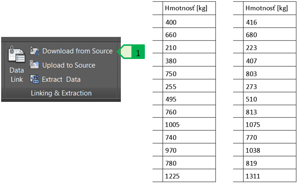
Fig. 101: Updating the data of the data link. Tool for data loading from the source file 1; original weight values (table on the left); new weight values (on the right).
The update of the data in the AutoCAD environment and the subsequent sending of the data to the source file requires a slightly different approach, as the data imported using the data link, or the imported table is inserted into the drawing so that the cell contents are locked, so first it is necessary to unlock the cells using the “Cell Locking” tool on the “Cell Format” panel on the “Table cell” tab. In this way, in the example we can unlock the cells with product descriptions and edit the product names “D07509” and “D07512” to “Shaft bottom - extended” (Fig. 102).
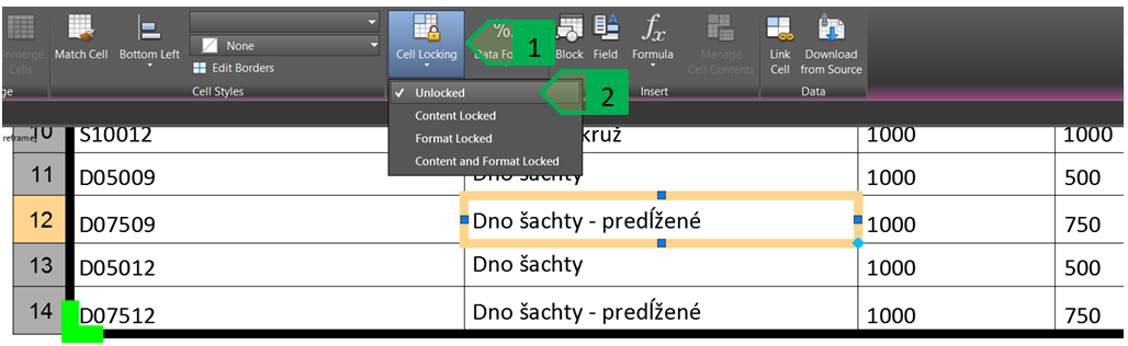
Fig. 102: Unlocking the locked cell linked through the data link, 1 - “Cell Locking” tool; 2 - setting the unlocking of the selected cell
Then the changes made in the AutoCAD environment can be sent into the source file and to update it using the “Upload to Source” tool on the “Linking & Extraction” tool on the “Insert” tab (Fig. 103). Before sending the data, this file must not be opened, otherwise the update of the source file will not be performed.
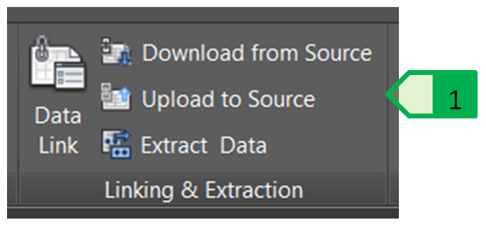
Fig. 103: Sending the changes into the source file, 1 - “Upload to Source” tool
Editing the linked table and using the formulas
The table object in the AutoCAD program can be extended by adding columns or rows. In case of tables linked to the MS Excel files, these tables can only be expanded outside of the linked parts of the table, so rows can only be added above and below the linked table, and the columns can only be added to the left and right of the linked table. If it is necessary to extend also the part of the linked table, you need to perform this extension in the MS Excel program. In case the data link is created with a link only to a specific part of the sheet, it is necessary to modify this range in the data link manager of the AutoCAD program, as adding a row or column moves the existing rows down and the existing columns to the right.
Various table operations can be performed, as needed, using the cells of the linked table. In case of the sewer system in Veľký Lapáš, we will expand the inserted table of the production range by adding two columns: a column with the number of pieces and a column with the total weight of the individual components, and adding a row with a summary of the total weight of all elements (Fig. 104).
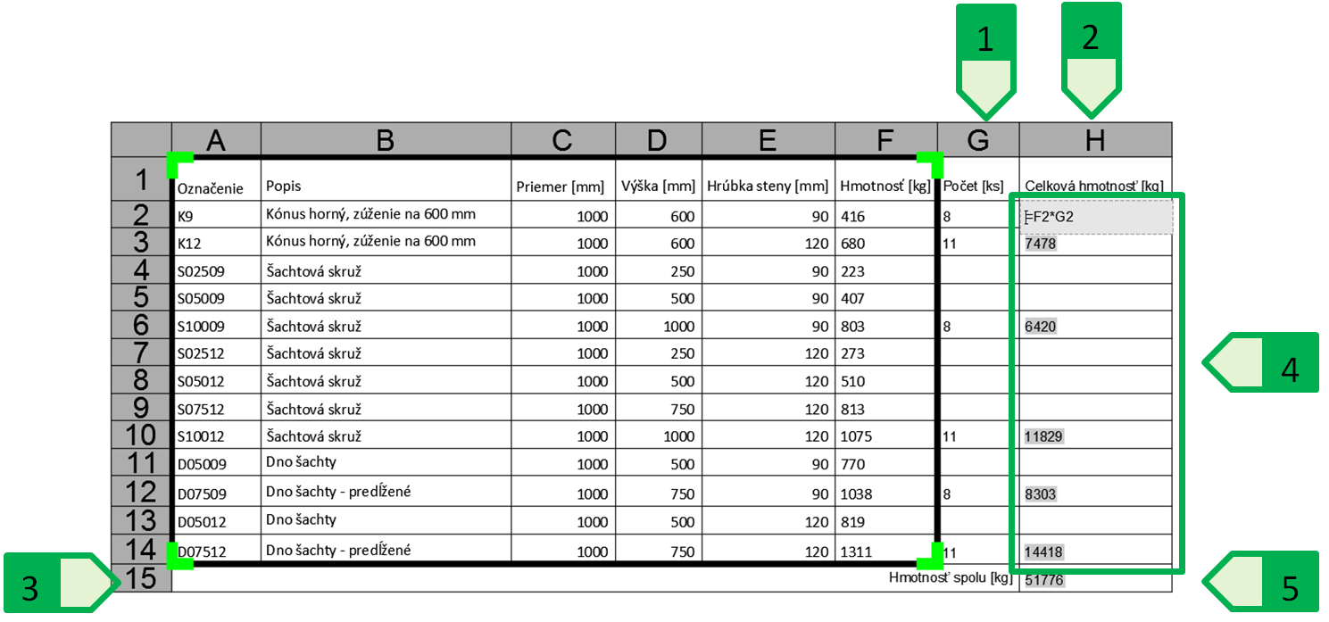
Fig. 104: Extending and using the formulas in the table linked to the MS Excel file. 1 - added column of the number of pieces; 2 - added column of the total weight of the individual components; 3 - added row of the total weight of all products; 4 - use of the formulas to calculate the weights of individual components (multiplication of the cell with the number of pieces and the cell with the weigh of one piece); 5 - using a formula to calculate the total weight of all components (sum of values from cells H2 to H14)